


Best viewed using:
Internet Explorer
or
Mozilla Firefox


Wiring Micro LEDs - Continued...
-
Figure 7 on the previous page shows the cathode (green) wire soldered to the cathode soldering pad. The next step is to trim off the excess tinned wire that hangs off the edge of the LED. Using micro scissors or a sharp scalpel, carefully trim off the excess wire even with the edge of the LED circuit board as shown in figure 8, below.
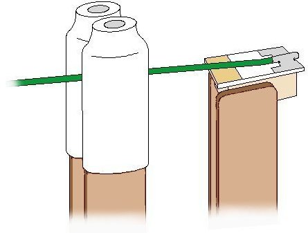
Figure 8
-
Open the padded clip and carefully route the green wire up, away from the Cathode solder pad as shown in figure 9, below.
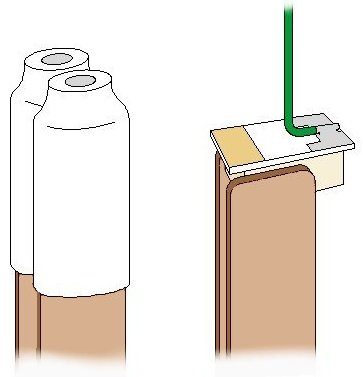
Figure 9
-
This process can be assisted by using a sharpened toothpick to help support the wire near the solder pad while pulling it up away from the back of the LED. See Figure 10 below.
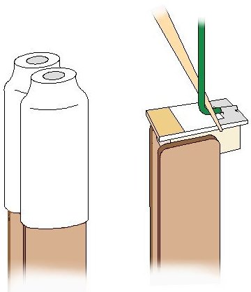
Figure 10
-
Next, we will release the unpadded clip while holding the green wire and using the wire as a "handle" rotate the LED so the other (anode) solder pad is facing left. Open the unpadded clip with you left hand and position the LED into the clip just like it was (slightly offset) before with the anode solder pad exposed past the right side of the clip, and release the clip. You may need to make tiny adjustments by holding the wire while reopening and closing the clip for best positioning. See Figure 11 below.
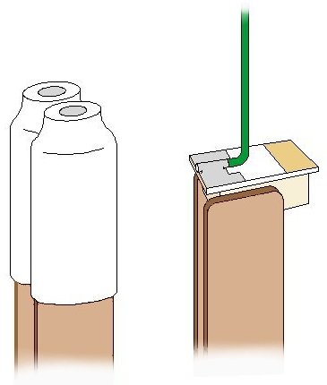
Figure 11
-
Now, perform the same procedures as above for the anode solder pad using a tinned segment of RED #38 magnet wire. See figures 12 through 14, below.
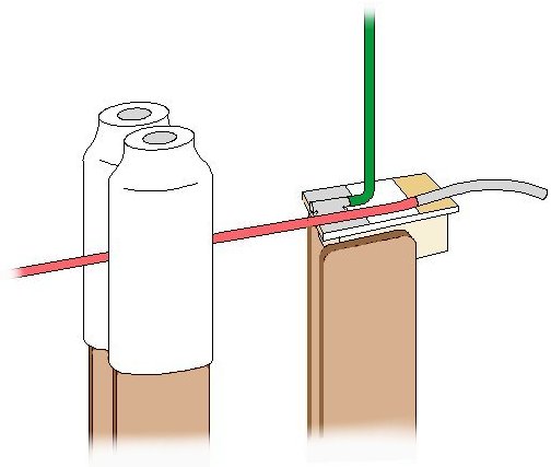
Figure 12
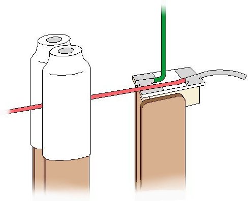
Figure 13
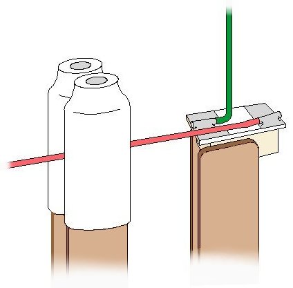
Figure 14
-
Finally, route red wire up away from the back of the LED as shown in Figure 15 below. The wires should exit the back of the LED parallel to each other with a close 90º bend in each wire so they lay flat on the LED back and then exit up and away as shown.
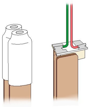
Figure 15
-
Should there be any residual liquid flux from soldering in the area between the solder pads, an easy way to soak up and remove the flux is by gently sliding a small cut piece of paper edgewise between the 2 wires so that it slides along the back of the LED. The paper is quite absorbent and very slightly abrasive, so it cleans that portion of the rear of the LED very nicely. See Figure 16, below.
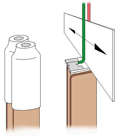
Figure 16
This completes the wiring process for Micro LEDs. In addition to "back wiring" as we've shown here, there are other wiring schemes that can be useful for various applications. They are covered in detail in our Advanced Lighting section for our Nano LEDs. A link to that topic is here.
Remember to thoroughly re-inspect the solder joints and be sure to test the wired LED prior to installation.
© 2008 Ngineering