


Best viewed using:
Internet Explorer
or
Mozilla Firefox


Advanced lighting techniques for Nano LEDs
For those of you that have ventured into the world of our Nano LEDs, you have undoubtedly discovered that these little jewels can truly open new frontiers to very sophisticated lighting that have previously been unavailable in the modeling environment. Because of their extreme small size, incredible intensity, and cold thermal properties, these little LEDs can be located nearly anywhere, regardless of the scale being modeled, and meet lighting needs only limited by your imagination.
One example of the benefits of small size can be seen with the modified N-scale grade crossing gate (N.J. International) we built to demonstrate one of our Simulators. A link to that page is here.
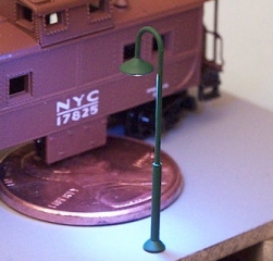
Another, would be this tiny Z-scale streetlight that casts a very nice flood of light. It houses a Nano-white LED up inside the scale 24" shade. The photo was taken with normal room lighting.
Whatever the project might be, if a light source of very miniature size with excellent brightness properties is required, these LEDs can usually meet or exceed all expectations.
Nano details
As we dig deeper into specific miniature lighting projects, the physical orientation of the LED will have a major impact on the lighting effect trying to be achieved.
A Nano LED is basically a small PC board with solder pads on one side (the back) with the tiny LED die (or chip; the part that gives off the light), mounted on the other side. This chip is then enclosed in a molded "house" of epoxy for protection. When power is applied through the solder pads, the chip emits a very bright light which shines out of the face, sides and ends of its epoxy "house". The location of the LED chip is slightly offset from center toward one end in all Nano LEDs. It is offset toward the cathode solder pad end of the LED (except with the RED LED this would be the anode end). Figure 1 below shows the basic orientation.
Figure 1
Wiring for your needs
Below are 4 different wiring schemes that can be used to position a Nano LED to serve a particular purpose. Figure 2 we call (for lack of a better term) "back wiring". The wires are routed directly away from the back of the LED. This is a useful method when the maximum amount light is needed from the LED. An example of this would be for the streetlight above. The LED is pulled up against the underside of the lampshade and faces downward. The additional "side-shine" from the LED is reflected off of the shade and maximizes the overall flood of light.
Note: You might think that pulling the LED's wires so that the LED back is up against (or almost against) the inside of the lampshade would cause the LED to short-out. As it turns out, that's not the case. It seems that getting the rectangularly-shaped LED back to make contact evenly enough with a somewhat conical/hemispherical shaped lampshade to short, is a near impossibility. After building more than 50 various street and building lights, we haven't gotten one to short out yet...
Depending on the project, the wires coming away from the LED can also be twisted if appearance calls for it. One example would be a early-era workbench light. Wire a Nano white LED, tint it slightly with clear orange acrylic paint. Twist the wires by holding them near the rear of the LED with a cushioned clip and twisting the other end until the desired twist is achieved. Run a brush with flat black acrylic paint over the twisted wire and let it dry. Punch a hole in a lampshade for the wire and paint the shade dark gray or green. Then drop it down over the LED. Viola... a workbench light.
Figure 2
Figure 3, we refer to as "side wiring". An example of this is the 3 Nano red LEDs we wired for the grade crossing gate mentioned above. In this application the gate is a brass casting and the top edge (where the lamp-like castings were) is quite rough. After removing the castings we had to file and sand the surface to smoothen it for LED mounting. Because the brass is conductive and the manufacturer used common-anode wiring in construction. The whole assembly (crossbuck, gate, etc.) must be considered "hot". That is, the plus DC connection is wired to the casting frame and can easily conduct through to the gate arm also. To protect the LEDs from shorting on the gate. We cut 3 small squares of .005" styrene and glued (CA) them to the top of the gate arm. We then glued the wired LEDs to the styrene squares, and finally routed and glued the wires along the back side of the gate. A little touch-up paint and the wires basically disappeared.
Figure 3
In Figure 4, we've wired the Nano LED using "end wiring". This particular method lends itself to some very interesting lighting possibilities that may not seem obvious at first.
Figure 4
You will recall that Figure 1 detailed the basic construction of the Nano LED and made note of the specific location of the LED chip within the device. When combined with end-wiring, the fact that this chip is located more toward one end of the LED actually creates a whole additional level of lighting possibilities that are almost scary.
OK... you've been working with Nano LED's for some time now and you really appreciate what their sub-miniature size will do for you. How about a half-Nano? Do you think it might open the door to yet more possibilities?
The LED chip is close enough to the end of the LED's epoxy "house" that the intensity of the light projecting out of that end, is nearly as bright as the intensity out of the face! A good example of this is our little diorama to demonstrate our Beacon Simulator (N8032). Figure 5, below is a close-up of the beacon head. We are at about the limits of our camera's magnification, but you can see the basic components of the Nano yellow LED sticking out of the end of the .042" tubing collar that houses it. Half of the LED is below the top surface of the collar. When the Simulator is running and we view the LED looking down from the top, it is bright enough to be seen from 75-100 feet away - even in normal room lighting! A Nano LED when viewed on-end is essentially one-half the size of the full LED. It's .020" wide by ~.026" high.
![]()
Figure 5
Another example would be our Rotating Beacon Simulator (N8042). Here, we have 3 LEDs organized in a triangular assembly being sequenced to simulate rotation. The effect is very realistic and in this case we painted the ends (facing up) of the LEDs black because their "top" shine actually detracted from the rotational effect. Figure 6, below shows a close-up of the painted LEDs mounted on the roof of an N-scale switcher. The 3 LEDs as a group are small enough to look the size of a scale roof beacon. To dress it up, we could put a thin metal collar around the base and "blob" the LEDs with some Crystal Clear Gallery Glass to form a beacon housing.
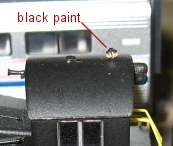
Figure 6
The rotating beacon uses the end-wiring method of wiring but is not really and example of "end-lighting", it is a case where we had to counter-act that effect to get what we want. There are many projects, especially in the smaller scales, where drilling a small hole and poking a Nano through (end of passenger car lights, class lights on diesels, marker buoys, etc.), sticking out of a piece of tubing, atop a small sawhorse for traffic control, etc, etc. The possibilities are endless.
Figure 7
Figure 7 above, we refer to as "daisy-chain" wiring. This special case lends itself nicely to strings of serially-wired LEDs. Imagine a string of red, yellow and green Nano LEDs between poles around a small used car lot. As long as the DC power source is sufficient that it's voltage exceeds the sum of the LEDs in the string (a protection resistor would be required), the number of LEDs could be as many as required.
And finally... smaller still
OK... now you think we've been skateboarding without a helmet again. Seriously, this is a very useful effect and quite easy to create.
Nano LEDs are quite bright (of course, they can easily be dimmed to any level), but part of the reason they appear so bright is that they are "point sources" of light to the unaided eye. That is, their light output is concentrated in a very small area and as a result appear in very high contrast when viewed.
Note: Never stare for any period of time into high intensity LEDs (of any color) especially with any magnification. The intense concentration of light can damage the retina in your eye.
OK, on to smaller still... Here's an example of utilizing a point source to a modeling advantage. Suppose you model Z-scale. From a fine detail standpoint, the concept will apply to any scale, but for this scenario... you model Z-scale, and... you want to make marker lights for a caboose. Yep, Z-scale marker lights.
Step 1, wire up a pair of Nano whites using "back wiring" (Fig. 2 above).
Step 2, put a few twists in the wires near the LED to keep them together and paint the whole LED, wires near the LED and all with a good acrylic black paint (Poly Scale Night Black comes to mind), and let it dry thoroughly so the moisture is gone and it can't possibly short the LED. A couple of coats of paint would be best for total coverage.
Step 3, Using tweezers or a nice smooth clip, hold the LED by the two ends and scratch off a small (preferably circular) area on each side and on the face of the LED near the end where the LED chip is located.
Step 4, Using Gallery Glass or Tamiya Clear acrylic, "blob" tiny drops of green and red over the scratched-off areas and let dry. You may have to hold the LED by the wires and retouch the black where the tweezers contacted the LED, in case the black got scratched during holding.
Step 5, Drill #80 holes in the rear corners of the caboose in the appropriate locations and thread the LED wires through the holes so that the LEDs are up against the caboose. Align the LEDs vertically and add a tiny dab of white glue to hold everything in position (once it dries). White glue is "repairable adhesive" where CA is not. A little water and it will soften and allow removal or repositioning.
Wire them up to the appropriate power source and you've got Z-scale marker lights that will have your fellow modelers saying "How in the......?"
There are many situations in modeling where using only a portion of an LEDs output is to an advantage. Two examples are using LEDs other than Nanos, but are worth noting to describe the point.
Figure 8, below is of an N-scale construction light we built using two 2x3 Super-white LEDs. We wanted to make sure light only shined from the face of the LEDs so we painted the sides and back of their ceramic housings with several coats of Poly Scale Night Black to totally eliminate the (quite bright) side and back-shine that is typical of these LEDs.
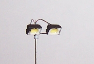
Figure 8
Figure 9 is of an N-scale intersection example with a 4-LED streetlight. The LEDs are Micro red and yellow and were painted all black. The faces were scraped to only permit front-shine.
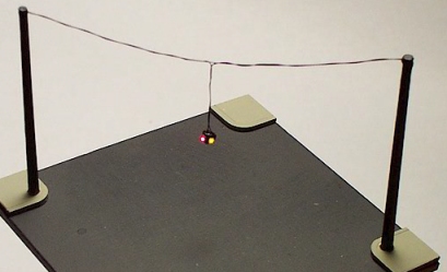
Figure 9
As you can see, there are many possible examples where only a portion of an LED's light may be needed.
In the case of the Z-scale marker light, above, the intent is to make the actual LED essentially unnoticeable so the eye is drawn to the tiny beads of light. In this way, they appear much smaller than the actual LED and can be tailored to a specific scale need.
© 2009 Ngineering