


Best viewed using:
Internet Explorer
or
Mozilla Firefox


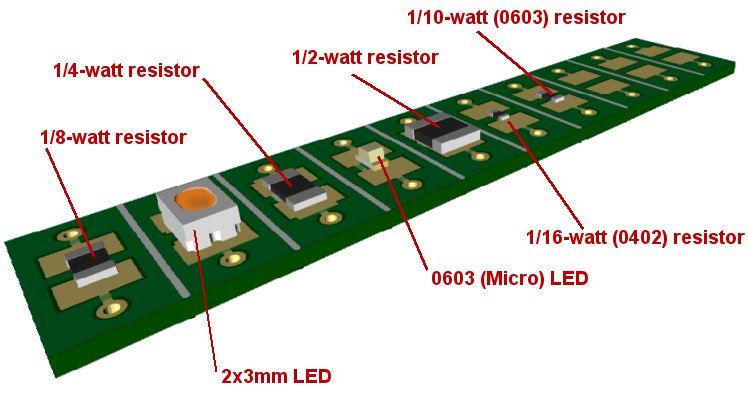
Above are various examples of components that can be mounted on our N8106 boards. Each board (10 per strip) has been v-scored so it can be easily snapped loose from the strip. The following procedure covers the step by step method to separate boards from the strip:
-
Decide how many boards are needed for a particular application. For example, for lighting, often times it is desirable to have a resistor-LED combination that can be mounted inside a structure or railroad rolling stock such as a passenger car. In this case a 2-board section should be removed from the strip.
-
Using a sharp scalpel blade or single-edged razor blade, slice the Kapton tape on the back of the strip across the strip directly over the v-score between the second and third board.
-
Once the tape is cut, grasp the strip holding the #2 and #3 boards and bend the strip. The boards will "snap" and separate at the v-scored groove between them
-
Now this 2-board section can be gently held by the ends in a bench vise (with padded jaws) in preparation for mounting components to the boards.
-
We recommend lightly tinning the solder pads on the boards before mounting and soldering components. This makes attaching the components much easier and quicker. This is especially beneficial when mounting thermally sensitive devices such as LEDs.
-
We strongly recommend using a low-temperature soldering iron with a needle tip and low-temperature solder for all soldering operations with these boards.
-
Once the pads have been pre-tinned place a small bit of solder on the tip of the needle tip of the iron. Using tweezers, pick up the component you want to mount on the board so that one end of the component can be placed on one of the solder pads with the component centered between the two pads. While holding the component in position, carefully touch the pre-tinned pad with the tip of the iron, allowing the small bit of solder on the tip to reflow the solder on the pre-tinned pad. This will be a quick operation so minimal heat will be transferred to the component and a shiny bright solder joint should result.
-
Now that one end of the component is soldered in position, repeat the above step for the other end of the component and other pad. Now that component is securely soldered to the mounting board.
-
If the component you mounted is an LED, be sure to remember that LEDs are polarity so it is important to know which end is the anode (+) and which is the cathode (-).
-
Once the second component has been soldered in position you now have a LED resistor combination that can be used for a lighting project. Since the LED and resistor must be wired in series with each other, a small jumper wire can be connected from one hole at the end of one pad to the appropriate hole one the adjacent board containing the other component.
-
Now power wires can be attached to the other pads using the holes located near those pads and the circuit will be complete.
-
Be sure to test the circuit before mounting it in the project.
-
When you are ready to mount the two-board circuit, simply peel off the protective Kapton from the back side of the mounting boards and stick them in position in your project.
© 2015 Ngineering