Best viewed using:
Internet Explorer
or
Mozilla Firefox
Adding switches to the LED Power Distribution Jr.
Figures below show front (current source) and back (resistor side) views of the N8105 Details are noted in red.
Adding switches to LEDs on the current source side of the board
If the series group has I, 2 or 3 LEDs in the group, then the switch wires
should be connected at the point where a solder bridge would be normally
placed to complete the circuit. If 4 LEDs are in the series, then the
cathode trace leading to the –DC rail for the 4th LED must be cut first.
Using a scalpel, cut completely through this trace in two places (as shown
in figure 4 – black lines), and peel the cut section of the trace away. This
will ensure there is enough of a gap to prevent any shorting. Solder switch
wires to the points shown by the two red lines.
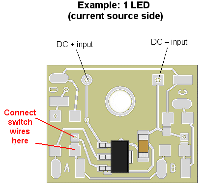
Figure 1
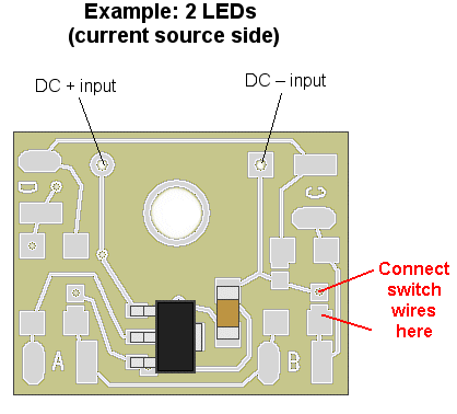
Figure 2
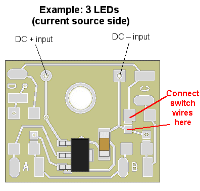
Figure 3
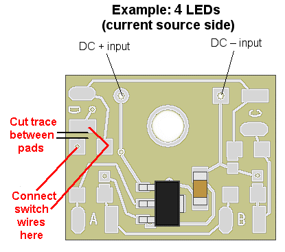
Figure 4
Adding switches to LEDs on the resistor side of the board
For the back (resistor) side of the board, if 1, 2 or 3 LEDs are used, the switch wires should be connected at the point where a solder bridge would be normally placed to complete the circuit (circled in red), or if it is a series group, at the last solder bridge in the group. See figure 5 below.
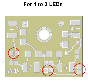
Figure 5
If a 4th LED will be used, then the cathode trace leading to the –DC rail for the 4th LED must be cut first. Using a scalpel, cut completely through this trace in two places (as shown in figure 6 – black lines), and peel the cut section of the trace away. This will ensure there is enough of a gap to prevent any shorting. Solder switch wires to the points shown by the two red lines. The resistor side of the board has the flexibility to allow virtually any combination of individual LEDs or series groups to be switch controlled.
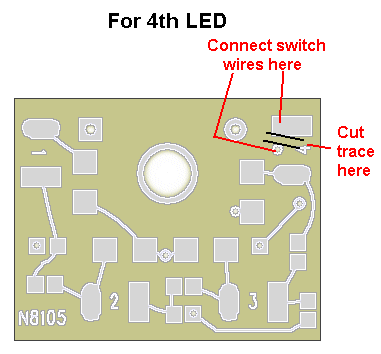
Figure 6
© 2012 Ngineering


