


Best viewed using:
Internet Explorer
or
Mozilla Firefox


N8103B High-current Smoke Generator Controller / Timer
TheN8103B has a physical size of 1.75" (44.45mm) x 0.75" (19.05mm) with a typical thickness of 0.200" (5.0mm).
The N8103B High-Current Controller/Timer is essentially a very high current switching circuit combined with one of our N8050 single output Simulators programmed as a timing circuit. The N8050 timer is mounted on the Current Control main board. The heart of the Current control board is a N-Channel HEXFET Power MOSFET that can act as a power switch to easily control up to 16 Amps of 12-volts DC. The main board also contains components to interface the power mosfet with the timer circuit.
How to use the N8103B:
The
N8103B is not a
power supply. It is a switch combined with a multi-selectable
timer. This module can switch up to 16 Amps of 12-volts DC,
BUT, can only
switch the Amperage available that is provided by the DC power supply connected
to it.
The
on-board (N8050) timer circuit is factory programmed with 3 different “on
times”. 3-minutes, 5-minutes and 10 minutes. These times are selected by
momentarily connecting solder pad “A” to either PAD “B’, “C” or “D”.. A
push-button switch wired between the pads works very well for this. We do offer
custom programming for the timing function if the customer has special
requirements. The main board also has a small blue LED that lights up when the
mosfet “switch” is energized.
Flexibility:
The
N8103B was designed primarily to function in a 12-volt DC environment, but it
can support a wider range of voltages from 7-volts DC to 18-volts DC.
Example of use:
One
example of use for the N8103B would be to run a modeling smoke generator. These
type of smoke units are essentially
a small heating unit that heats a type of oil in a container that produces smoke
in a scale model environment. As the heater runs it gradually consumes the
available oil and must be turned off to prevent damage to the heating element
when it runs dry.
Other
examples might be switching on a series of LED lights or turning on a small pump
for a model waterfall. There are many possibilities.
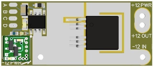
Figure
1
above,
shows the
general layout of the N8103B module with the timer N8050 Simulator mounted on
the main board.
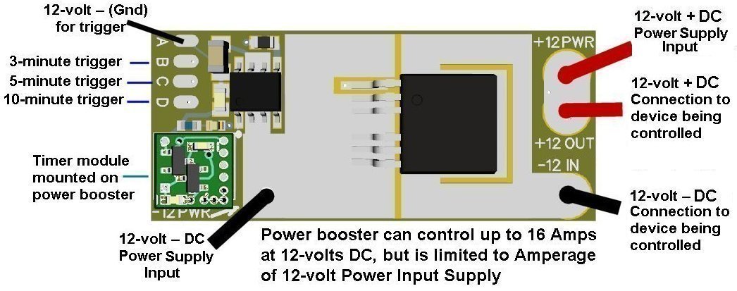
Timer wiring:
Located at the end of the main board are 4 solder pads labeled “A” thru “D”. The
“A” pad is the ground (–DC) connection and the “B” pad is for triggering a
3-minute switched “on-time” for the module. Wiring a push-button switch between
these two solder pads will start the 3-minute time when the push-button is
pushed.
For a 5-minute on-time, wire between “A” and “C” pads. For a 10-minute on-time
wire between “A” and “D” pads.
Power Supply input connections to the board are labeled “12-volt + DC Power
Input” for the power supply + DC, and “12-volt – DC Power Input” for the –DC.
Figure 2 shows an example of a device being
switched by the N8103B board.. Shown are two additional wires that are connected
to the board that come from the device being switched
Important:
Do not
mix up the connection of these two
wires with the power input wires that come from the Power Supply. Circuit damage
and even the possibility of a
fire could occur due to the high current of this circuit.
Power wire sizes:
If your project needs to switch 5 Amps at 12 volts DC you should use 16AWG wire
size.
If you need to switch 10 Amps you should use 14AWG wire.
If you need to switch 16 Amps you can use 14AWG for 3-foot runs of 12AWG for
runs of up to 20 feet.
When soldering power wires to the board use low-temperature solder & flux. Apply
sufficient heat for good solder joints but be careful to not overheat the
circuit board.
Board mounting:
Included in this package is a double-sided
sticky foam pad for mounting the main board. Just peal off the protective paper
on each side and mount the board to any flat surface.
Note:
Six soldered
electrical connections protrude through the bottom side of the main board under
the Timer Module. Make sure when mounting the main board that these six
connections
do NOT
contact any
metal material which could cause a short circuit.