


Best viewed using:
Internet Explorer
or
Mozilla Firefox


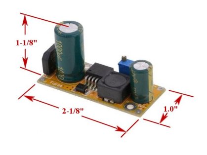
Note: The height dimension is from the board bottom surface to
the top of the large capacitor. An additional 1/8" space under the
bottom should be allowed for clearance of soldered component leads that
are clipped off and protrude below the board bottom surface. Two mounting holes
are provided and spacers or small fiber washers can be used to elevate the board
so the clipped protruding leads cannot touch any mounting surface
Alternately, double-sided sticky foam mounting tape can be used providing the
foam thickness is at least 1/8" and the adhesive is a high-strength bonding type
that will not easily come loose.
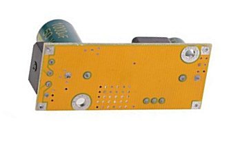
The picture below shows the bottom side
of the circuit board for reference. If the mounting holes are to be used, the
easiest way to properly locate the holes is to simply set the circuit on the
surface to be mounted and mark through the holes using a pen or pencil. These
marks can then be drilled in the mounting surface for screws and nuts or
self-tapping screws depending on the application.
© 2018 Ngineering