Best viewed using:
Internet Explorer
or
Mozilla Firefox
Adding switches to the LED Power Distribution Board
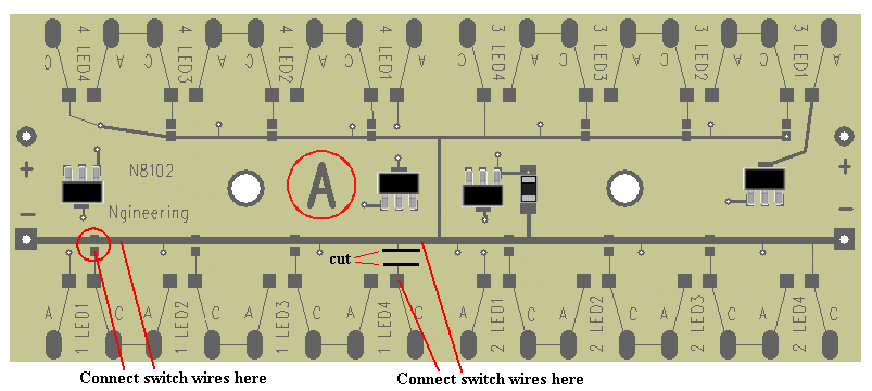
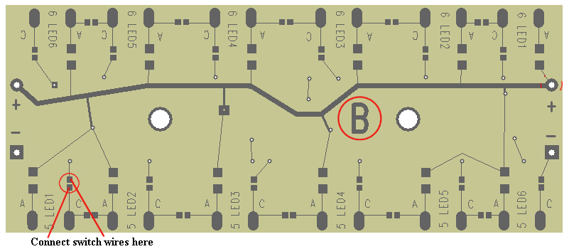
Figures 1 & 2 show front and back views of the N8102. Details are noted by a red circled area and corresponding comments.
Adding switches to LEDs on Side A of the board
For side A, if any of the series groups to be switched has 4 LEDs,
then a very slight board modification is required. For example, if an A-side
series group has I, 2 or 3 LEDs in the group, then the switch wires should
be connected at the point circled in red where a solder bridge would be
normally placed to complete the circuit. If 4 LEDs are in the series, then
the cathode trace leading to the –DC rail for the 4th LED must be cut first.
Using a scalpel, cut completely through this trace in two places (as shown
in figure 1 – black lines), and peel the cut section of the trace away. This
will ensure there is enough of a gap to prevent any shorting. Solder switch
wires to the points shown by the two red lines.

Figure 1
Adding switches to LEDs on Side B of the board
For side B, the switch wires would be connected at the point shown circled in red in figure 2 below, for each individual LED, or the last LED in a series group. Side B has the flexibility to allow virtually any combination of individual LEDs or series groups to be switch controlled.

Figure 2
© 2008 Ngineering


