


Best viewed using:
Internet Explorer
or
Mozilla Firefox


Drone Navigation Lighting Simulator installation
The
NLD8110-02 provides a tiny, low-voltage/low-current circuit which produces
navigation lighting for many different drone craft. Five 3mm LED lights are
provided: 2 white for alternate flashing LEDs for the drone front, 1 red LED for
port mounting, 1 green LED for starboard mounting, both flashing and a steady-on
white LED for rear mounting. All pre-wired circuitry and LEDs are included in
the package, plus a small copper-plated clip that can be used as a heat sink for
LED soldering. Also included is a 4” length of shrink tubing & a small
double-sided sticky foam pad for circuit mounting.
Utilizing
the
one of the
industry’s
most advanced
microcontrollers
and
highly regulated
voltage control circuitry, this
total module consumes less than
35ma of current during normal operation with all LEDs attached. Input DC voltage
range is 3.4 to 18 volts.
This
NLD8110-02
has all wires pre-stripped & tinned and pre-soldered to the circuit board
as well as the solder jumpers for on-board LED current control resistors
pre-soldered.
Figure 1
below shows a detailed view of the attached wires as viewed from the front side
of the circuit board.
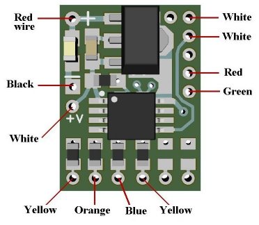
Figure 1
2 -
Preparing and soldering the LEDs:
Note: If pre-wired small surface-mount type LEDs are being used, Figure 5 below can be used as a reference for LED color placement and polarity connections.
A low-wattage iron (15-watt or less) should be used for this process and a needle type pointed tip should be used for connection of the LEDs to the wires.
Included in this package is a small smooth-jawed
alligator clip. This clip can be used as a heat sink during the 3mm LED
soldering process. These LEDs are very sensitive to excessive heat and using the
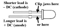
heat sink will help prevent any heat damage during the soldering process. Figure
2 below shows where to place the alligator clip on the LED leads prior to
soldering. The leads can be cut shorter if needed, but not shorter than the
“bump” on each lead. If cutting be sure to remember which is the + (anode) lead.
Figure 3 shows the electrical symbol for an LED denoting the DC polarity
connections. This symbol will be used in the wiring diagram Figure 4 .
![]()
Figure 2 Figure 3
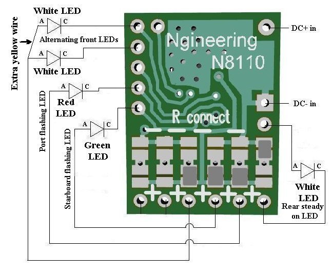
Figure 4
...A shameless promotion...
Should you not
have the soldering tools necessary to perform the previous steps, our 12-watt
N40M2 soldering iron with the N408I tip is perfect for these operation and we
also have N4200 low-temperature 2% silver solder and N4500 no-clean liquid
soldering flux for easy soldering...
3 -
Testing and
mounting the assembly:
At this
point, the Navigation Light Simulator assembly is completed and should be tested
prior to installation in the drone. Figure 2 on page 2 shows
red and black wires soldered on the left side of the circuit (front
view). These two wires are for power input and should be connected to your drone
battery.
NOTE: This
module DOES NOT HAVE
reverse polarity power protection, so be extra careful when connecting the
+DC RED
wire and the
–DC BLACK wire to your power
source. Connecting the backwards
will
damage the module.
Once power
has been applied and all LEDs appear to be function normally, the assembly can
be mounted into your drone. Included in this package is a small double-sided
sticky foam pad. Peel one of the protective backings off of the pad and stick it
to the bottom side of the module. The foam will help electrically insulate the
module from contact with any metal parts of the drone.
This
completes assembly of the Drone Navigation Lighting Kit.
© 2022 Ngineering