


Best viewed using:
Internet Explorer
or
Mozilla Firefox


Connecting the N8108-01 4-way Intersection Signal Simulator
Product & installation overview:
This
N8108-01 is designed to
provide centralized
connection for LEDs and series wired LED pairs connected to pad pairs
A through
H, which simulate a 4-way traffic
intersection with timed lighting
effects. DC power input is to be connected to the
DC+
and
DC–
solder pads as indicated in Fig.1 below.
This module is not designed for filament
type
bulbs.
Utilizing the one of the
industry’s
most advanced
microcontrollers and
highly regulated voltage control
circuitry, this
total module consumes less than
140ma of
current during normal operation with all LEDs attached. The 8-component
switching buck regulator circuit maintains on-board power regulation
within 2% while input voltage can range from 7.5 to 20 volts DC.
All connected LEDs are supported by on-board resistors for current
protection (and brightness balancing & control), so wiring is very
simple.
Connecting the
N8108-01:
The
module’s tiny size and thin construction will allow it to be placed so it is easily hidden
from view. The module
only
has circuitry on
the board top side. The bottom of the board is electrically –DC and can
be used for mounting with the small square double-sided sticky foam pad
that is included in this package.
Included with the module are
three 6” lengths of #32 insulated wire (red, black & violet).
These can be used for power input wires & control wires.
If used, the red wire should be soldered to the +DC solder pad, the black
to the –DC pad. The violet wire can be used for grounding (–DC) pad
M to initiate the signal effect.
Important note:
A
low-wattage
iron with a pointed tip should be used for connection of wires. Too much
heat or solder can easily damage the wires
or module and void the warranty.
When
connecting the
wired
LEDs, proper polarity must be observed. LEDs
are “polarity sensitive” and will not function if connected backwards. The
N8108-01 is designed to provide for easy visual determination of proper
LED polarity. As shown in Figure 1, There are solder pad pairs on the
board designated as A, B, A2, C, D, E, F, G
and
H. The
oval shaped pads are for
+
(anode) LED connections, and the
rectangular pads are for the –
(cathode) LED connections.
NOTE: This module is designed for connection of 20ma LEDs. It does not support filament type incandescent bulbs.
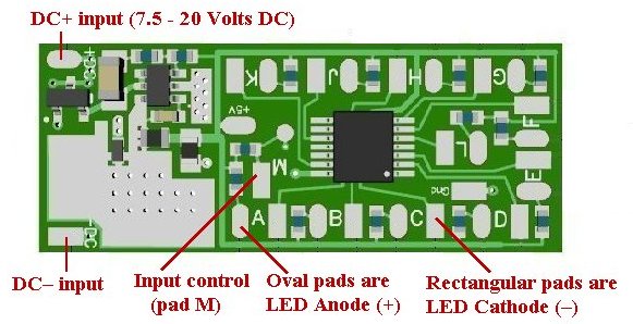
Figure 1
N8108-01 program configuration:
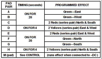
CONTROL:
Grounding (–DC) pad M momentarily will allow the traffic signal sequence to cycle through one time. Continuously grounding pad M will allow the intersection to loop continuously.
Figure 2 below shows LED wiring connections to pad pairs for the 4-way
traffic intersection
Simulator board.
Series wired LED pairs are individually wired LEDs with the first LED
cathode (–) connected to the second LED anode (+) This connection
(soldering of the 2 wires) can be located at any point under the
display. Be sure to insulate the soldered connection of these wires.
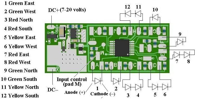
Figure 2
This completes hookup of our N8108-01 Intersection Signal module. We hope the added realism it provides enhances your enjoyment of the hobby.
© 2020 Ngineering