


Best viewed using:
Internet Explorer
or
Mozilla Firefox


Connecting the N8074 School Bus Simulator
Installing
the N8074 is very straightforward. Because the module has circuitry on both
sides, care must be taken to be sure that the components or wires soldered will
not make contact with any metal object and cause a short
circuit.
Included with the module are two 6” lengths of #32 insulated wire. If
necessary, these can be used for power input wires. If used, we recommend the
red wire be used for the + DC connection. It would be connected to solder point
1
as shown in Fig. 1. This wire could also connect through a switch to the + DC
connection for remote control of the lighting effect. The other (black) wire
should be connected to – DC and to solder point
2.
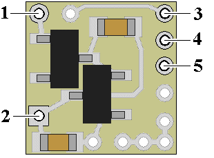
Figure 1
Important note: A low-wattage iron with a pointed tip should be used for connection of wires. Too much heat or solder can easily damage the wires or module and void the warranty.
Also, all connecting wires should be pre-tinned before soldering them to the module. This will make connection quick and easy and ensure excessive heat is not applied to the solder points.
Track powering (without a decoder connection)
All of our Simulators require a clean DC voltage of known polarity for their power source. Track power is typically provided in one of two forms. DC voltage (analog), or DCC.
Analog track power has been around for more than 75 years. Simply put, a DC voltage is applied to the two tracks with one being +DC and the other, -DC. Increase the voltage and the electric motor in the locomotive spins faster making the train go faster. If the train is required to reverse, track polarity is reversed so the loco's motor turns in reverse. Also, what defines "forward and reverse" is dependent on which way the loco is facing when it's put on the track. Bottom line here is that track polarity is not fixed. Our Simulator needs fixed polarity.
DCC track power is such that to devices requiring plain DC voltage, it looks like AC power. That is because voltage levels on each track go both + and – continuously. The DCC decoders in locomotives “descramble” the track signals and provide correct polarity so their motors can function normally. It is this process that will allow multiple locomotives to go in different directions on the same section of track, at the same time (a feature not available with analog track power). Once again, our Simulator needs fixed polarity and it needs to look like DC voltage.
Due to our Simulator's very small size, there is insufficient space to include additional circuitry and components necessary for proper power conditioning when direct track pickup is to be used. There are two solutions to this problem and both are inexpensive:
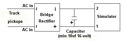
Discrete components
The Simulator can be powered from the track with the addition of two readily available components: a bridge rectifier (our N301S or N302S will work just fine). If DCC operation is used, the addition of a filter capacitor (10μf or larger and minimum 16-volt) will be required. Figure 2 below is schematic diagram of the connections required.
Figure 2
This is the least expensive solution, but is has a couple of minor drawbacks. First, the bridge rectifier (and capacitor, if needed) are not mounted on a circuit board so direct solder connection is required and you will need to ensure the pins on the rectifier and leads on the capacitor (depending on the type of capacitor) are organized so that they won't short out against anything. Second, depending on the physical size of the bridge selected (and capacitor, if needed) and the scale you're modeling, hiding these additional components so they're not noticeable can be a bit of a challenge.
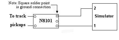
N8101 DC Power Source
A more elegant, but very slightly more costly ($3.95) solution would be to use our N8101 DC Power Source. It has all of the components needed, includes a circuit board with solder points, is extremely tiny (1/2 the size of our Simulator), has the lowest possible voltage loss (important for analog operators). Click here for more information on the N8101. Figure 3 below is schematic diagram of the connections required.
Figure 3
Connecting LEDs
When
connecting the LEDs, proper polarity must be observed. LEDs are “polarity
sensitive” and will not function if connected backwards.
The N8074 is configured for connection of four series pairs of 20 ma
LEDs. Each pair consists of two yellow (amber) LEDs (typical device voltage of
2.0 VDC), or two red LEDs (typical device voltage of
1.75-2.0 VDC).
Because this circuit controls the LED pairs by alternately changing the outputs 3– 5 from + to – , to high-impedance state (not connected), external resistors are required for current protection of the LEDs. Included with this module, are 5 1/8-watt 300-ohm SMD resistors (2 are spares) and 5 1/8-watt 150-ohm SMD resistors (also 2 spares). Either can be used for LED current protection. The 300-ohm resistors will dim down the LEDs appropriately for smaller scale usage (N & Z scale) The 150-ohm will allow the LEDs to be brighter for larger scale usage (HO & O). See Fig. 4 below for a schematic layout of LED hookup.
Included in
the package is a 5-position resistor mounting board that will greatly simplify
LED and resistor connections for all of the wiring. This is especially helpful
when all components (including the simulator) are placed inside of the school
bus model. This mounting board has double-sided Kapton®
tape mounted on the rear for easy attachment inside the model.
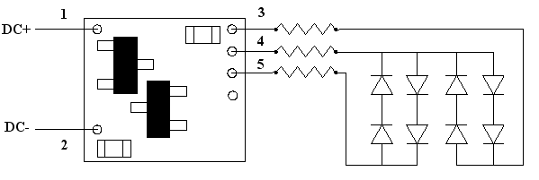
Figure 4
Using wire
appropriate for the size of the LEDs and their placement in the model, connect
wires to all 8 LEDs. It is recommended that different color wires be used for
each LED’s anode (+) & cathode (–) connections. Our N5038 wire comes in red and
green for this purpose. Wire lengths will be dependant on the size of the school
bus model. As a rule of thumb: 2-3 inches for Z & N scale models, and 5-7 inches
for HO & O scale models. Note: Red SMD LEDs are backwards form all other LED in
that their “cathode mark is really the anode.
A typical school bus has 8 large warning lights (4 in front & 4 at the rear) at
the roof-line of the bus at the outer most corners. Again, typically, red is the
outermost light and amber (or yellow) is mounted inside of each red. With 8 LEDs
there will be 16 wires & proper connection can be confusing. We try to simplify
this hookup using some abbreviations and diagrams. See Fig. 5 below:
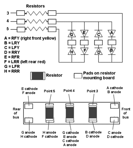
Figure 5
As you can
see in Fig. 5, we have labeled each LED and coded the LED positions on the bus
for easy identification. The resistor mounting board shown in the bottom of Fig.
5 notes the locations of the 3 resistors and which LED wires should be connected
to each solder pad on the board.
This wiring is easiest to perform if the wire ends are pretinned and twisted
together (then re-soldered) before attaching them to the solder pads on the
mounting board. This is especially true for the 4 wires attached to one pad
where the resistor is for the simulator solder point
4.
We
recommend testing each wired LED at several points during the project assembly:
-
After
they are wired
-
After
installation and gluing into position in the holes in the bus shell.
-
After
wiring to the resistor mounting board before the simulator is connected.
This completes connection of the N8074 module. It is recommended that a thorough re-inspection of all connections and module placement be performed prior to applying power to the locomotive. We hope you enjoy the added realism our module provides.
© 2016 Ngineering