


Best viewed using:
Internet Explorer
or
Mozilla Firefox


Connecting the NK032 Star Trek TOS Starships Lighting Kit for 1:1500 scale &
larger models
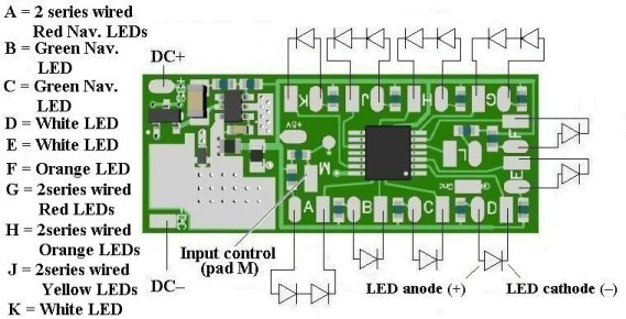
The primary circuit LED wiring layout and power/control connections are detailed
in Figure 1 below.
The second (smaller) circuit produces visual effects for TOS Photon Torpedo initialization (red LED) and firing sequence (white LED). An additional output is configured for (blue LED) Phaser firing. There are separate input controls to fire each weapon. These circuits are configured for LEDs and not designed for use with (filament) type bulbs. Please click on the following link: NCC-1701 Photon torpedo & Phaser Simulator for wiring and LED connection details for the secondary circuit board.
Preparing the primary circuit board:
Important
note:
Figure 1 shows a detailed view of the wires to be connected as viewed from the
front side of the circuit board.
Soldering wires to the circuit
module:
Included in this package are
2 red, 2 black & 3 violet wires.
red and black wires are for power input connections
and the violet wires are for circuit control functions. These wires should be
stripped and tinned prior to attachment to the circuit modules. Strip
approximately 1/8” of insulation from each end of each wire and ensure the wire
strands are twisted together and carefully tin each end.
When
soldering the power & control wirs to this circuit
good lighting, magnification, and a method to hold
the circuit while soldering will be very helpful in the positioning of the
wires.
As
shown in Figure 1, the 10 LED outputs support connections for a total of 14
LEDs. Four of these connections are configured for series connected LED pairs.
More detailed information on this will follow later.
Lighting (LED) output timing sequence
When power is applied (7 to 20 volts DC) to the primary board the following
startup sequence occurs:
A 2-second pause, then
Navigation lights (2 red Port LED & 2 green
Starboard LEDs turn on for 1-1/2 seconds and off for 1/2 second, then repeat.
A 4 second pause, then 2
white LEDs turn on for Bridge/Sensory/Engineering
Hull/Saucer section lighting.
A 4 second pause, then the Impulse Engine (Orange LED) turns on and Warp
Nacelles (2 red, 2 orange & 2 yellow LEDs) start activation.
A 4 second pause, then a white LED turns on for the saucer I.D. NCC-1701 display
5- Connecting LEDs to the primary circuit board:
Extra care must be taken when soldering wires in position.
Because of their close proximity, excess solder can cause bridging and short
circuits.
For best success in soldering the wires,
lightly pre-tin each solder pad & If the LED wires are single-strand magnet
wires, ensure they are properly stripped
and pre-tinned
prior to soldering them in place.
Again, it is highly recommended that a soldering iron of
15-watts or less be used
for all soldering operations on these two circuit
boards. Ngineering stocks soldering equipment and accessories specifically
designed to aid in these type of soldering operations. Our N4200 low-temperature
solder and N4500 no-clean soldering flux are perfect for this type of process.
When connecting LED magnet wires, It is easiest if a small
amount of solder is placed on the soldering iron tip first, then the wire is
placed in position and flux is applied . Carefully touch the soldering iron tip
to the solder pad/wire junction. This soldering process should only take about
1/3 of a second to provide a clean shiny solder joint with no excessive solder.
Repeat this process for all remaining wires.
Wiring Series
connected LEDs:
Figure 1 shows four series pairs of LEDs. This is a schematic representation showing LED symbols connected in daisy –chained fashion (cathode to anode). The length of the cathode to anode connection may in fact be fairly long due to the relative location of the two LEDs in the model.
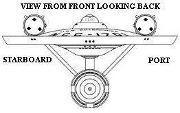
For example: when wiring the Warp Nacelles there will be 3 wires that join the 3 series pairs of red, orange & yellow LEDs with one of each color in each Nacelle. Figure 2 below shows a front view of the Enterprise NCC-1701
Notice that we have placed 3 small dots in the front of each Nacelle at
12:o’clock, 4 o'clock & 8 o’clock
positions. For proper lighting rotation of the
Bussard Collectors, the starboard collector rotates clockwise and the
port collector rotates counter-clockwise.
The primary
circuit board has connections for 10 LED outputs, + & –DC power inputs and one
control input.
In general, the primary circuit board contains 11 pad pairs labeled “A”
through “K”. Each pad pair has an oval pad & a rectangular pad. As shown in
figure 1, the oval pads are for connection an LED anode (+). The rectangular
pads are for LED cathode (–) connections.
To
properly place the correct LEDs in
their positions in the Bussard Collectors, the two series wired
RED
LEDs should be located in the 12 o’clock (top) position. Since both RED LEDs powered from position
“G” pad
pairs on the primary circuit turn on at the same time, this is not a problem .
Here
is a suggested wiring scheme that can
be used if the primary board is located in the saucer section of the
model:
1. If
you are using our N5038 red & green magnet wire, run a red wire from the oval “G” pad (+ connection) down the support for
the saucer section to the main hull and up through the starboard
support to the starboard Nacelle and connect it to the anode connection
of a red LED and locate that LED in the 12 o’clock position in that Bussard
collector.
2. Run
a green wire from that LED’s cathode (–) back down through the Nacelle support
to the main hull and up through the port
Nacelle support to the port Nacelle and connect it to the second RED
LED’s anode (+) connection at the 12 o’clock position in the port Bussard
collector.
3.
Now, run another green wire from the Port RED LED’s cathode (–) connection
back down the Nacelle support, through the main hull and up through the
support to the saucer section and connect it to the rectangular “G” (–) pad.
This
completes the circuit for the two RED series wired LEDs for the Nacelles.
To
properly place the ORANGE LEDs in
their positions in the Bussard Collectors, the same
procedure as in 1 through 3 above can be used with the following changes:
You
will be wiring from the “H” pad pairs
and the LED locations in the Bussard collectors are slightly different.
The
starboard ORANGE LED must be located
in the 4 o’clock position and the port ORANGE LED is located in the 8 o’clock
position.
To
properly place the YELLOW LEDs in
their positions in the Bussard Collectors, the same
procedure as in 1 through 3 above can be used with the following changes:
You
will be wiring from the “J” pad pairs
and the LED locations in the Bussard collectors are slightly different.
The
starboard YELLOW LED must be located
in the 8 o’clock position and the port YELLOW LED is located in the 4 o’clock
position.
The
above LED placement ensures that both Bussard Collectors simulate proper
rotation of the LED effects.
The
other series wired LED pair is for the two RED LED Navigation lights located on
the saucer ‘s port side. The cathode to anode connection will be very short and
is wired to the circuit position “A” as shown
in Figure 1.
Wiring
additional LEDs:
The “B” & “C” pad pairs on the primary board are for connecting 2 GREEN
starboard Navigation LEDs. These LEDs & WHITE & BLUE LEDs have high device
voltages than RED, ORANGE or YELLOW LEDs so they cannot be wired in series pairs
for the primary board’s outputs.
The “D” & “E” pad pairs are for two WHITE LEDS for
Bridge/Sensory/Engineering Hull/Saucer section lighting.
The “F” pad pair is for an ORANGE LED for the Impulse Engine. Correct positioning is shown in Figure 3 below:
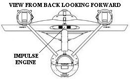
Figure 3
The “K” pad
pair is for a WHITE LED for the saucer I.D. Light
on the top-front of the saucer.
Wiring the control input pad:
The rectangular pad “M”
is for input control to initiate the lighting startup sequence. One of the
violet wires can be used for this connection.
Lighting
startup is initiated by momentarily grounding (–DC) this pad. Once the startup
sequence begins, it will continue to run until power to the circuit boards is
removed. This can be achieved by placing a toggle switch in the power input +DC
connection.
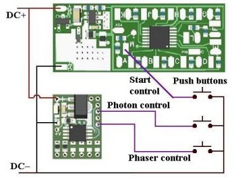
Power & control wiring for the two circuit boards:
Figure 4 below shows the power and control wiring for the primary and secondary (Photon & Phaser) circuit boards. Again, Please click on the following link: NCC-1701 Photon torpedo & Phaser Simulator for wiring and LED connection details for the secondary circuit board.
Included
with this package are two red, two black and two additional violet wires These
can be used for power input & control wiring. Also shown are 3 push-button
switches with one side of each connected to the 3 control (violet) wires and the
other side connected to DC–. These push buttons can be located anywhere that is
convenient for the modeling display.
This completes wiring of the two-board assembly. They should be tested prior to installation.
We hope the added realism
these simulator circuits
provide
enhances
the realism and
your enjoyment of the hobby.
© 2022 Ngineering