


Best viewed using:
Internet Explorer
or
Mozilla Firefox


NLD8110-03 Dual-Marslight Simulator Effect and Installation
Description of Lighting Effects
This
NLD8110-03 provides a tiny,
low-voltage/low-current circuit which produces a dual
Marslight simulation that runs for two 20ma
white family (white, incandescent, yellow-white, golden-white) LEDs
in simultaneous operation.
All solder connections explained below
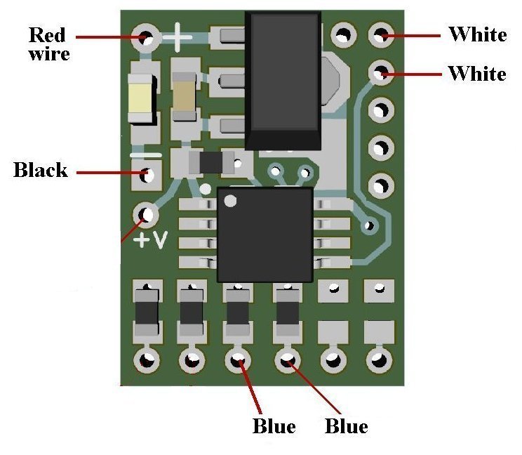
Figure 1
NLD8110-03 (DCC/RC) input power connections:
The NLD8110-03 Simulator is
configured for DCC environments and sound decoders having 3.3-volt
accessory functions. Since track polarity is not a factor in DCC the
need for DC polarity protection is not required. Also, in an RC
modeling environment, battery power is known so this is not an issue.
However, since this family of
Simulators
doesn't have polarity protection, care must be taken during wiring to
ensure polarity is correct before power is applied. Otherwise, the
circuitry
will be damaged.
Figure 1 above shows a detailed view of the locations of the wires to be
attached as viewed from the front side of the circuit board. These wire
are included in this package.
Utilizing the
one of the
industry’s
most advanced
microcontrollers
and
highly regulated
voltage control circuitry, this
total module consumes less than
40ma of current during normal operation with all LEDs attached. Input DC
voltage range is 3.4 to 20 volts.
Preparing
the
NLD8110-03:
The
module’s tiny size
and thin construction will allow it to be placed so it is easily hidden
from view. The module has circuitry
both sides so care must be taken when mounting to prevent
contact with metal (electrically conductive) material which could
cause a short circuit. The bottom of the circuit board can be used for
mounting with the small square double-sided sticky foam pad that is
included.
Important note:
A
low-wattage
iron (15-watt or less) should be used for this process and a
needle type pointed tip should be used for connection of the
wires
to the module. Too much heat or solder can
damage the wires,
LEDs
&
module and void warranty.
Figure 1 above shows a detailed view of the locations of the wires to be
attached as viewed from the front side of the circuit board. These wire
are included in this package.
Soldering wires to the module:
Each
of the six wires should be stripped and tinned prior to attachment to
the circuit module. Strip approximately 1/4” of insulation from each end
of each wire, ensure the wire strands are twisted together and carefully
tin each end.
Each
wire’s tinned end should be inserted into the appropriate solder point
as shown above, with the wire inserted from the front side of the board
and soldered on the back side of the board. For this process, good
lighting, magnification, and a method to hold the circuit while
soldering with be very helpful in proper positioning of the wires.
Extra care must be taken when soldering these wires in position.
Because of their close proximity, excess solder can easily cause
bridging between pads.
Soldering wires to the module—continued:
For best success in soldering the wires,
place each wire into the appropriate solder hole and seat the insulation
up against the hole on the front side of the board. Ensure the wire is
held in that position when applying
any flux and solder to the hole on the back side of the board.
It is easiest if a small amount of solder is placed on the
soldering iron tip first, then the wire is placed in position and flux
is applied at the back side
of the hole. While holding the wire in position, touch the tinned wire
strand and the hole with the soldering iron tip allowing the solder to
flow into the hole capturing the wire. This soldering process should
only take about 1/3 of a second to provide a clean shiny solder joint
with no excessive solder. Then, carefully snip the protruding wire from
the solder joint. This will ensure a good joint and eliminate possible
shorting. Repeat this process for all remaining wires.
Again,
a
low-wattage
iron
(15-watt or less) should be used for this process and a needle type
pointed tip should be used for connection of the LEDs to the wires.
...A shameless promotion...
Should you not have the soldering tools necessary to perform the
previous steps, our 12-watt N40M2 soldering iron with the N408I tip is
perfect for these operation and we also have N4200 low-temperature 2%
silver solder and N4500 no-clean liquid soldering flux for easy
soldering...
Testing and mounting the assembly:
At
this point, the NLD8110-03 Simulator assembly is completed and should be
tested prior to installation. Figure 2 below shows
red and black wires soldered on the right side of the circuit
(rear view). These two wires are for power input and should be connected
to your power source.
REMINDER:
This module DOES NOT HAVE
reverse polarity power protection, so be extra careful when connecting
the +DC RED
wire and the –DC BLACK
wire to your power source. Connecting the backwards
will damage the module.
Once
power has been applied and all LEDs appear to be function normally, the
assembly can be mounted into your project.
Included in this package is a small double-sided sticky foam pad.
Peel one of the protective backings off of the pad and stick it to the
bottom side of the module. The foam will help electrically insulate the
module from contact with any metal parts.
LED
symbols shown indicate “A” (anode +DC) & “C” (cathode –DC) connections.
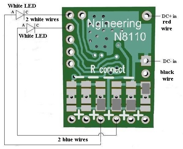
Figure 2
This completes connection of the NLD8110-03 module. It is recommended that a thorough re-inspection of all connections and module placement be performed prior to applying power to your model. We hope you enjoy the added realism our module provides.
© 2025 Ngineering