


Best viewed using:
Internet Explorer
or
Mozilla Firefox


NLD8062A & NLD8062B Navigation Simulator Effect and Installation
Description of Lighting Effects
This simulator is programmed to run a red LED beacon (varies in intensity to simulate rotational effect), and 1 green and 1 red LED configured as strobes for wingtips for the NLD8062A, or the NLD8062B with a white LED beacon with green & red wingtip strobes. Timing of the beacon is approximately once per second, and after every second cycle the strobes pulse for a short 25ms burst. This mimics many tail beacons and wingtip strobes seen on WW2 and modern aircraft.
All solder connections explained below
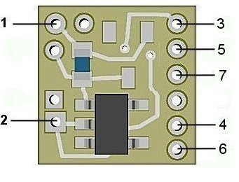
Figure 1
NLD8062A & B (DCC/RC) input power connections:
The NLD8062A & B Simulators are configured for DCC environments and sound decoders having 3.3-volt accessory functions They have an on-board jumper in place of the barrier diode used in the analog version. This allows them to operate fully at 3.3-volts (even slightly, below allowing for LED brightness). Since track polarity is not a factor in DCC the need for this protection is not required. Also, in an RC modeling environment, battery power is known so this is not an issue. However, since this family of Simulators doesn't have polarity protection, care must be taken during wiring to ensure polarity is correct before power is applied. Otherwise, the circuitry will be damaged. Figure 2 below shows the front side of the NLD8062A & B with the jumper installed and the barrier diode not installed.
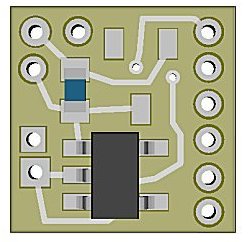
Figure 2
Important note: A low-wattage iron with a pointed tip should be used for connection of wires. Too much heat or solder can easily damage the wires or module and void the warranty.
Also, all connecting wires should be pre-tinned before soldering them to the module. This will make connection quick and easy and ensure excessive heat is not applied to the solder points.
Solder point #2 is the -DC (or ground) power connection.
Unlike our traditional Simulators, these new low-voltage modules have two on-board current limiting resistors. The second resistor can be connected either to the circuit's +DC voltage or to it's –DC (ground) by solder jumpering either of two pairs of jumper pads on the rear-side of the module. Figure 2 below show the location of the resistors and solder jumper pads. Never place solder on both pairs of jumper pads, this would destroy the Simulator. See Fig. 3 below for a complete overview.
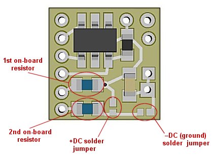
Figure 3
For the NLD8062A & B Simulators to function correctly, place a small blob of solder across the +DC (plus DC) jumper pads. This will ensure the connected LEDs will have their anodes connected to a +DC voltage supply.
Connecting LEDs
When connecting the LEDs, proper polarity must be observed. LEDs are “polarity sensitive” and will not function if connected backwards. The NLD8062A & NLD8062B modules are configured for one simulated beacon effect and two wingtip strobe effects. The NLD8062A is configured for one 20ma Red LED with a device voltage of 1.75-2.0 volts DC (Ngineering’s Micro, Nano & 3mm red LEDs) for the beacon. The NLD8062B is configured for one 20ma white LED with a device voltage of 3.0-3.3 volts DC (Ngineering’s Micro, Nano & 3mm white LEDs) for the beacon. This LED will use one of the on-board current limiting resistors so it can be wired directly. Additionally, both versions are configured for two wingtip strobe lights. One Green for the starboard wingtip with a device voltage of 3.0-3.3 volts DC (Ngineering's Micro, Nano & 3mm signal green LEDs), and one Red for the port wingtip with a device voltage of 1.75-2.0 volts DC (Ngineering's Micro, Nano & 3mm red LEDs). See Fig. 4 below for wiring layout.
Using wire appropriate for the size of the LEDs and its placement in the model, connect the appropriate beacon LED to the simulator module as shown below. Connect the cathode wire (the – connection) of the LED to point 3 on the module and connect the anode wire of the pair (the +) to solder point 4.
The next two (2) LED connections will be for the wingtip strobe lights. Connect the green LED's anode to point 6 and its cathode to point 7. Connect the red strobe LED's cathode to point 5 and its anode to point 6.
Figure 4
Once again, be sure to use a low-wattage soldering iron when connecting wires to the module. Our N40M2 12-watt Iron with either the N408I (iron clad) Needle Tip, or the N408X (bare copper) Needle Tip would be an excellent choice for this operation.
This completes connection of the NLD8062A & B modules. It is recommended that a thorough re-inspection of all connections and module placement be performed prior to applying power to your model. We hope you enjoy the added realism our module provides.
© 2020 Ngineering