Best viewed using:
Internet Explorer
or
Mozilla Firefox


Connecting the L8047 Latching Campfire Simulator & N8X0X-084 Campfire Sound effect
Product &
installation overview:
The
L8047 is designed to generate enhanced lighting effects for either 2
series-wired LEDs or a single LED connected to its outputs (solder points
3 & 4) when power is
applied to the inputs (points
1& 2), and will simulate the random flicker of a crackling campfire or
fireplace. This module is not designed for incandescent (filament) type bulbs.
The L8047 is programmed with correct timing to function with our N830X-084 or N850X-084 Sound modules.
Utilizing
the industry’s smallest
microcontroller and associated voltage control circuitry, the total module
consumes less than 1/2 ma. Typical peak operating current with the LED attached
and running is about 18 ma. This makes
it ideally suited for operation with batteries, or any well-filtered and
regulated DC power source with an output of 6-18VDC.
Connecting the L8047:
Installing
the L8047is very straightforward. Its tiny size and thin construction
will allow it to be adapted to nearly any modeling scale.
Because the module has circuitry on both sides, care must be taken to be
sure that the components or wires soldered will not make contact with any metal
object which could cause a short
circuit.
Included
with the module are three 6” lengths of #32 insulated wire. If desired,
these can be used for power input & control wires. In this case, the red wire
can be connected to solder point
1
(the +DC connection) and the black wire can be connected to solder point
2 (DC-). The violet wire can be connected to point
6
for input control. See Fig. 1 below.
Important
note:
A
low-wattage iron with a pointed tip should be used for connection of wires. Too
much heat or solder can easily damage the wires, decoder or module and void the
warranty.
Also, all
connecting wires should be pre-tinned before soldering them to the module. This
will make connection quick and easy and ensure excessive heat is not applied to
the solder points.
When
connecting the LEDs, proper polarity must be observed. LEDs are “polarity
sensitive” and will not function if connected backwards
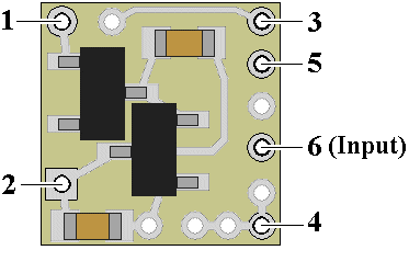
Figure 1
When
connecting the LEDs, proper polarity must be observed. LEDs are “polarity
sensitive” and will not function if connected backwards.
The
L8047
is configured to connect two series-wired 20 ma yellow LEDs with device voltages
of 2.0 VDC between solder points
3
&
4.
(this covers all of Ngineering’s yellow LEDs, as well as most yellow LEDs
available). These LEDs will use the
L8047’s
on-board current protection resistor.
Use wire
appropriate for the size of the LED and its placement in the model. For two
LEDs, connect the first LED
anode
(the +
connection) to solder point 4.
Connect the
cathode
(- connection) of this LED to the
anode
of the second LED and connect the
cathode
(- connection) of the second LED to solder point
3. For a single LED, connect one side of a 100-ohm resistor (supplied
in this package with a spare) to solder point 4.
Connect the other side of the resistor to the
anode
of the LED. Connect the LED
cathode
to point
3.
Figure 2
(below) is a schematic diagram of the connections required.
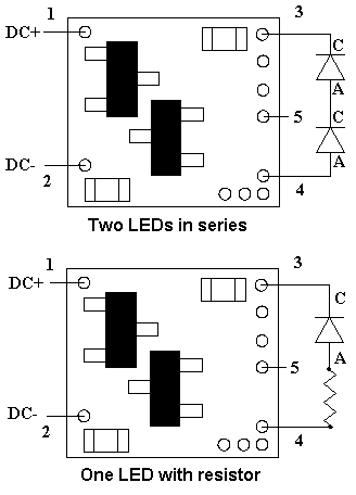
Figure 2
Connection with N830X-084 Little Sounds Modules

Connection with N850X-084 Little Bigger Sounds Modules