


Best viewed using:
Internet Explorer
or
Mozilla Firefox


Connecting the NLA8039 Steam Locomotive Class Light Simulator for 3.3-volt green & white LEDs
I
Product &
installation overview:
The NLA8039 is designed to allow sequential
control of LEDs connected to its outputs (solder points
3 - 7) when power is applied to the inputs
(points
1& 2). Control is sequenced
(stepped) by grounding (-DC) of solder point
8. See Class light Operation below for detailed information.. This module is not designed for use with
incandescent (filament) type lamps.
Utilizing the industry’s smallest
microcontroller and associated voltage control circuitry, the total module
consumes less than 1/2 ma. Typical peak operating current with both LEDs
attached and running is about 38 ma. This makes the NLA8039 ideally
suited for operation when directly powered by a function output of today’s
HO, N or Z-scale DCC decoders, or any well-filtered and regulated DC
power source with an output of 3.4-16VDC.
If analog
(non-DCC) track operation is desired, our N8101 Analog DC Power Source (sold
separately) can be used to provide power.
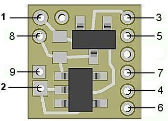
Figure 1
Important note: A low-wattage iron with a pointed tip should be used for connection of wires. Too much heat or solder can easily damage the wires, decoder or module and void the warranty.
Also, all connecting wires should be pre-tinned before soldering them to the module. This will make connection quick and easy and ensure excessive heat is not applied to the solder points.
Connecting the NLA8039:
Installing
the NLA8039 is very straightforward. Its tiny
size and thin construction will allow it to be placed in many spaces too small
for even the smallest Z-scale
decoder. Because the module has
circuitry on both sides, care must be taken to be sure that the components or
wires soldered will not make contact with any metal object (such as a locomotive
frame) causing a short circuit.
Included with
the module are three 6” lengths of #32 insulated wire. If necessary, these can
be used for power input and function control wires.
Most wired
decoders have a blue wire which is the common connection for all wired functions
(F0, F1, etc.). It is the + DC connection and will be connected to solder point
1 as shown in Fig. 1
If the
decoder is a “drop-in” style without wires, consult the decoder manual and use
the blue wire supplied to connect point #1 to the appropriate + solder pad. If the solder pad has a resistor in series with it, be sure
to connect the blue wire behind the resistor (see Fig. 2).
Figure 2
Next, choose
the function you want to use to power the class light simulator and connect the
appropriate function wire to solder point
2. For example: If you want F1 to power the simulator, connect the green
wire to point
2.
Again, if the decoder is the drop-in style, use the enclosed green wire to connect the appropriate function solder pad to #2. Make sure the pad chosen for this connection is not a “+” pad , but a function pad (– DC ). Whichever function you choose, make sure it is programmed for On/Off control only. Do not program the function for special effects. The NLA8039 will control the special effects.
Direct Track powering (without a decoder connection)
All of our Simulators require a clean DC voltage of known polarity for their power source. Track power is typically provided in one of two forms. DC voltage (analog), or DCC.
Analog track power has been around for more than 75 years. Simply put, a DC voltage is applied to the two tracks with one being +DC and the other, -DC. Increase the voltage and the electric motor in the locomotive spins faster making the train go faster. If the train is required to reverse, track polarity is reversed so the loco's motor turns in reverse. Also, what defines "forward and reverse" is dependent on which way the loco is facing when it's put on the track. Bottom line here is that track polarity is not fixed. Our Simulator needs fixed polarity.
DCC track power is such that to devices requiring plain DC voltage, it looks like AC power. That is because voltage levels on each track go both + and – continuously. The DCC decoders in locomotives “descramble” the track signals and provide correct polarity so their motors can function normally. It is this process that will allow multiple locomotives to go in different directions on the same section of track, at the same time (a feature not available with analog track power). Once again, our Simulator needs fixed polarity and it needs to look like DC voltage.
Due to our Simulator's very small size, there is insufficient space to include additional circuitry and components necessary for proper power conditioning when direct track pickup is to be used. There are two solutions to this problem and both are inexpensive:
Discrete components
The Simulator can be powered from the track with the addition of two readily available components: a bridge rectifier (our N301S or N302S will work just fine). If DCC operation is used, the addition of a filter capacitor (10μf or larger and minimum 16-volt) will be required. Figure 3 below is schematic diagram of the connections required.
Figure 3
This is the least expensive solution, but is has a couple of minor drawbacks. First, the bridge rectifier (and capacitor, if needed) are not mounted on a circuit board so direct solder connection is required and you will need to ensure the pins on the rectifier and leads on the capacitor (depending on the type of capacitor) are organized so that they won't short out against anything. Second, depending on the physical size of the bridge selected (and capacitor, if needed) and the scale you're modeling, hiding these additional components so they're not noticeable can be a bit of a challenge.
N8101 DC Power Source
A more elegant, but very slightly more costly ($3.95) solution would be to use our N8101 DC Power Source. It has all of the components needed, includes a circuit board with solder points, is extremely tiny (1/2 the size of our Simulator), has the lowest possible voltage loss (important for analog operators). Click here for more information on the N8101. Figure 4 below is schematic diagram of the connections required.
Figure 4
Connecting LEDs
When
connecting the LEDs, proper polarity must be observed. LEDs are “polarity
sensitive” and will not function if connected backwards.
The NLA8039 is configured to connect
four LEDs in
groups of two series pairs. Figure 3 on the back of this instruction show the
wiring layout for these LEDs. The first LED in each pair is a 20 ma
white
LEDs with
device voltage of
3.3 VDC. This
covers Ngineering’s
N1011
Micro and
N1031
Nano
white
LEDs, as well as many
3.3-VDC white LEDs available.. These LEDs symbols are marked with the letter
W.
The second
LED in each series pair is a 20ma signal-green LED
with device voltage
of
3.3 VDC. This covers Ngineering’s
N1017
Micro and
N1037 Nano
signal-green
LEDs, as well as
many
3.3-VDC signal-green
LEDs available.
These LEDs symbols are marked with the letter
G.
A s shown in Fig. 3 the Anode (+) of each white LED is connected to solder points 4 & 6. Power for these two LEDs are provided thru the on-board current limiting resistors
Figure 5
Each
signal-green LED is wired with its anode (+) connected to the cathode (-) of one
of the white LEDs. The cathode (-) of each signal-green LED is then wired to an
external 81-ohm resistor which is then connected to solder point 2 (-DC).
Included with this module are
three
of these
resistors (we’ve included a spare just in case) .These
resistors
have
pre-tinned tabs so soldering is easy.
The junction
of each series pair has an additional wire connected between the white LED
cathode and green LED anode. These two wires are connected to solder points
3
& 5.
They serve as voltage polarity control to determine whether no light, white
light or green light is outputted from the circuit.
See Fig. 5.
Once again,
use
a low-wattage soldering iron when connecting wires
& LEDs.
Input control
Solder point
7
on the simulator module is for connection of the control or function input wire.
This can be connected to either a momentary throttle function such as F2, or any
on/off decoder function (F1, F3, F4, etc.). This simulator can handle either
type of control input. If an on/off function is selected for hookup, again, be
sure the decoder has special effects turned
off.
Solder
points 8 (+) & point 9 (-) are for
connection of external capacitors if required for flicker control
Unlike our
traditional
Simulators,
these new low-voltage modules have
two
on-board current limiting resistors. The second resistor can be connected either
to the circuit's +DC voltage or to it's –DC (ground) by solder jumpering
either
of two pairs of jumper pads on the rear-side of the module. Figure 6 shows the
location of the resistors and solder jumper pads.
Never
place solder on
both pairs
of jumper pads, this would
destroy
the Simulator.
For the Class Light Simulator to function correctly, place a small blob of
solder across the
+DC
jumper pads. This will ensure proper LED power connection.
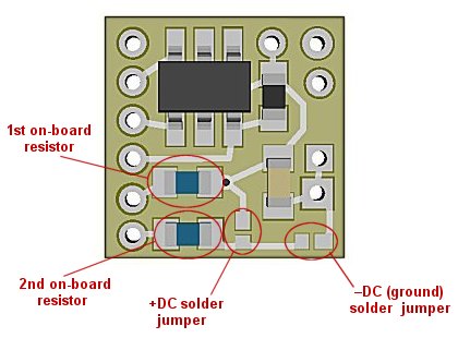
Figure 6
Step by step Class Light Operation:
-
When the Simulator is powered-up all LED outputs are off to simulate the most common (dark) Class Light mode. Typical for a scheduled train.
-
Taking the input to ground (-DC) either momentarily or holding it there turns on the Green LEDs. (A scheduled train with a 2nd section following).
-
These will stay lighted until the input is released from ground and re-grounded. The and condition simulates a pushbutton being pushed a second time (or a switch being turned off and back on again).
-
Once the input is re-grounded, the Green LEDs turn off and the White LEDs turn on (for trains running an extra).
-
These will stay lighted until the input is released from ground and re-grounded.
-
When the input is re-grounded the White LEDs turn off and all Class Light LEDs are off.
-
When the input is released and again re-grounded we go back to step 2 (Green LEDs on).
This completes hookup of our NLA8039 Steam Locomotive Class Light module. We hope the added realism it provides enhances your enjoyment of the hobby.
© 2022 Ngineering