



















Best viewed using:
Internet Explorer
or
Mozilla Firefox


Connecting the NLA8044 & NLD8044 Unmarked Police Car Simulator
Installing the NLA8044 or NLD8044 is very straightforward. Its tiny size and thin construction will allow it to be placed in many spaces too small for even the smallest Z-scale decoder. Because the module has circuitry on both sides, care must be taken to be sure that the components or wires soldered will not make contact with any metal object (such as a locomotive frame) causing a short circuit.
Included with the module are three 6” lengths of #32 insulated wire. If necessary, these can be used for power input and function control wires.
NLA8044 (analog) input power connections:
The NLA8044 Simulator is configured for analog (DC) operating environments. It will function normally with input voltages ranging from 3.2 to 16-volts DC. The circuit includes a Schottky barrier diode to protect the module from reverse input voltage polarity. If using DC track power,this means when it is wired the normal "engineer's side is the +DC track side", the effect is fully operational. when running in reverse "fireman's side is the +DC track side) the effect is not in operation. For many lighting effects, this will not be a problem because they are intended for forward operation.
For those effects that need full bi-directional operation, one of our N8101 DC Power Source circuits can be added in front of the effect simulator board to eliminate DC polarity issues. The N8101 contains a very-low voltage-drop Schottky bridge rectifier which will slightly raise the startup voltage threshold of the lighting effect by about 0.2-0.4 volts. Figure 2 below below is schematic diagram of the connections required.
All solder connections explained below
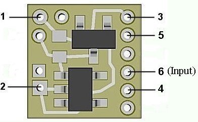
Figure 1
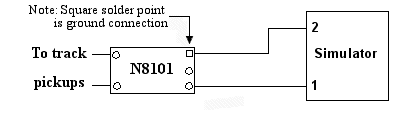
Figure 2
NLD8044 (DCC/RC) input power connections:
The NLD8044 is configured for DCC environments and sound decoders having 3.3-volt accessory functions They have an on-board jumper in place of the barrier diode used in the analog version. This allows them to operate fully at 3.3-volts (even slightly, below allowing for LED brightness). Since track polarity is not a factor in DCC the need for this protection is not required. Also, in an RC modeling environment, battery power is known so this is not an issue. However, since this family of Simulators doesn't have polarity protection, care must be taken during wiring to ensure polarity is correct before power is applied. Otherwise, the circuitry will be damaged. Figure 3 below shows the front side of the NLD8044 with the jumper installed and the barrier diode not installed.
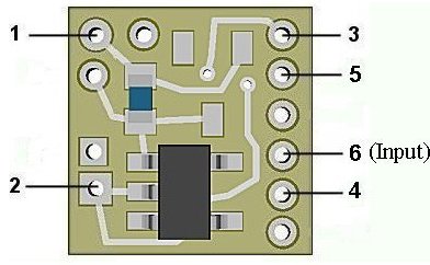
Figure 3
In a DCC environment, most wired decoders have a blue wire which is the common connection for all wired functions (F0, F1, etc.). It is the + DC connection and will be connected to solder point #1 as shown in Fig. 1.
If the decoder is a “drop-in” style without wires, consult the decoder manual and use the blue wire supplied to connect point #1 to the appropriate + solder pad.
If the solder pad has a resistor in series with it, be sure to connect the blue wire behind the resistor (see Fig. 4). This will ensure full voltage is supplied to the module.
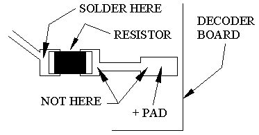
Important note: A low-wattage iron with a pointed tip should be used for connection of wires. Too much heat or solder can easily damage the wires, decoder or module and void the warranty.
Also, all connecting wires should be pre-tinned before soldering them to the module. This will make connection quick and easy and ensure excessive heat is not applied to the solder points.
Next, choose the function you want to control the NLA/NLD8044 module and connect the appropriate function wire to solder point #2. For example: If you want F1 to turn on the Strobe lights, connect the green wire to #2.
Again, if the decoder is the drop-in style, use the enclosed green wire to connect the appropriate function solder pad to #2. Make sure the pad chosen for this connection is not a “+” pad , but a function pad (– DC connection).
Whichever function you choose, make sure it is programmed for On/Off control only. Do not program the function for special effects. The NLA8044 or NLD8044 will control the special effects.
Connecting LEDs to the N8044
When connecting the LEDs, proper polarity must be observed. LEDs are “polarity sensitive” and will not function if connected backwards. The N8044 is configured for the "common-anode" connection of two 20ma LEDs. The most common LED colors for this application is one red LED and one blue LED. Ngineering's Nano, or Micro LEDs are ideal for this choice. The NLA8044 & NLD8044 have on-board current limiting resistance to protect these LEDs so no external resistor is required.
Common-anode wiring refers to 2 or more LEDs that share a single connection (wire) to their anodes (+DC connections).
Using wire appropriate for the size of the LED and its placement in the modeling project, connect the 2 LED anodes (the A connections) together and wire that junction to solder point 4 on the module. Connect one LED cathode (the C) to solder point 3. Connect the other LED cathode (-) to solder point 5. See Fig. 2 below for a schematic layout of LED hookup.
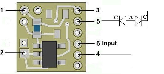
Figure 5
Once again, be sure to use a low-wattage soldering iron when connecting wires to the module. Our N40M2 12-watt Iron with either the N408I (iron clad) Needle Tip, or the N408X (bare copper) Needle Tip would be an excellent choice for this operation (or any DCC decoder work).
Input control
Solder point 6 on the simulator module is for connection of the (optional) input control wire. This additional control can be connected to either a momentary throttle function such as F2, or any on/off decoder function (F1, F3, F4, etc.). This simulator can handle either type of control input. If an on/off function is selected for hookup, be sure the decoder has any special effects turned off for that function. The simulator module will take care of the effects.
For non-decoder installations or for analog operation, solder point 6 can be connected to any switch (momentary pushbutton or magnetic reed switch) which is tied to -DC (ground).
This completes hookup of our NLA8044 & NLD8044 Unmarked Police Car modules. We hope the added realism it provides enhances your enjoyment of the hobby.
© 2026 Ngineering