


Best viewed using:
Internet Explorer
or
Mozilla Firefox


Connecting the NK030 Lightning effects Kit
This kit
includes a pre-programmed simulator, a 2-channel N8103A-2 Super Booster board
with the simulator installed on it and two high-intensity (300 lumen) 1-watt
12-volt white LEDs with wired sockets, plus power input and control wires. A
1/2-inch square double-sided adhesive foam pad is included for mounting the
booster board.
The Lightning
effect is designed as an add-on for our N8502-030 Little Bigger Sounds
Thunderstorm sound effect, but can be used separately (as stand-alone lightning)
if so desired.
Wiring this
kit for operation:
Figure 1 below
shows the layout of the N8301A-2 Super Booster board with the Lightning light
effect Simulator board mounted on it (small board on the left side. Included
with this kit are two #26 wires for use as power input wires. The red wire
should be soldered to the +DC IN solder point (just above the left-side of the
Simulator board, and the black wire soldered to the –DC IN point just below the
Simulator board.
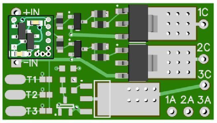
Figure 1
CAUTION! The included LEDs are
extremely bright and are intended for INDIRECT viewing ONLY.
Prolonged direct viewing can seriously damage your eyes
The
two socketed LEDs included in the kit create the very bright lightning
flashes that are triggered by the simulator board and amplified by the
Super Booster channels 1 & 2.
Booster
channel
1 output solder points are labeled
1C and
1A. This channel is for the “foreground” lightning effect. Channel
2 output points are labeled
2C and
2A and are for the “background” lightning which is lower in intensity being
for a more distant effect.
In
most diorama and layout applications, the thunder and lightning will be
somewhat distant from the front viewing position and the LEDs should be
located to shine
INDIRECTLY up against a
backdrop or some surface that will give reflectability when the flashes
occur. The distance is totally dependant on layout or diorama size and
configuration, but from a wiring standpoint, we recommend limiting wire
length to a maximum of 12-feet, with our preference being about 6-feet
to minimize voltage drop from the booster to the LEDs. Wire used for
this extension should be at least #26 in size. When wiring the LEDs, the
Red wire is the + connection and must be connected to the
“A”
solder points. The black wires connect to
the
“C”
solder points. Included in this kit a 4 segment of shrink tubing that can
be used to cover solder
joints for the splicing of longer wires to the LEDs.
Connecting control wires to run the Lightning effect:
Important note:
A low-wattage iron with a pointed tip should be used for connection of these
wires. Too much heat or solder can damage the circuit pads on the board and void
the warranty.
In the lower left corner of the Super Booster there are 3 oval pads labeled T1,
T2 & T3. (see Fig. 2 below) To the right of each pad is a pair of solder jumper
(bridging) pads These bridging pads will
NOT
be used for this application.
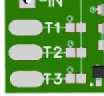
Figure 2
Oval padT3:
This pad is connected to the
lightning Simulator’s control input
and when connected to ground (–DC) , starts the lightning effect. Included in
this kit is a #32 violet wire that can be used for this connection.
If the Lightning effect is to be used with the N8502-030 Thunderstorm Little
Bigger Sound effect, the blue wire in that product package is normally connected
to control pad #3 on the sound module (see Fig 3 below). When that wire is
grounded (–DC) it starts the sound
effect.
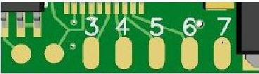
Figure 3
To synchronize the Lightning and Thunder, connect both control wires together
and momentarily connect the to –DC. This will initiate both effect which will
run for 1 minute and 23 seconds and stop. This –DC connection
must
be the same –DC that connects to the power inputs for this booster board and the
Little Bigger Sound effects modules.
If you plan to run these effects using one of our N8600 Proximity Detectors,
the control wires should be connected to the
Switched DC
output marked on that circuit board.
Looping or, continuously running the effects:
There may be
situations where it is desirable to have the Lightning and Thunder run longer or
run in a continuous loop. If that is desired, the violet and blue wires
mentioned above would be grounded (–DC) continuously instead of momentarily . A
toggle switch works well for this purpose. We have also included two additional
(yellow) wires that need to be connected if looping is desired. One end of one
yellow wire would be soldered to the “T2”
pad on the booster (Fig.2 above) and the other end connected to
pad #7
on the sound board (Fig. 3 above).
Because
both the Lightning Simulator and the Sound module have their own
microcontrollers with internal clocking circuits there can be a slight “drift”
in timing between the two boards. To eliminate this “drift”, the Simulator sends
out a momentary pulse at the end of its lightning cycle to oval pad
T2
that is transmitted to Sound board
pad #7
causing the sound processor to do a reset (start over at the beginning). At the
same time the program in the Simulator starts over.
Unfortunately, when the sound board is reset the Little Bigger Sound
Amplifier board is still on and a “popping sound” will be heard in the speaker.
To eliminate this, the second
yellow wire needs to be connected between
“T2”
and one side of a 10K-ohm resistor on the
Amplifier board.
See Figure 4 below.
Be very careful when connecting to this resistor so as not to
overheat or cause solder to jumper (short) to other components or circuit
traces.
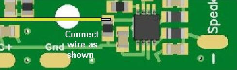
Figure 4
This completes connection of the NK030 Lightning Kit. It is recommended that a thorough re-inspection of all connections and module placement be performed prior to applying power. We hope you enjoy the added realism our kit provides.
© 2019 Ngineering