


Best viewed using:
Internet Explorer
or
Mozilla Firefox


Using the N8600 Proximity Detector
Wiring
options:
The
N8600 has two pairs of solder pads for power connection. One pair is on the
INPUT
(left side) of the circuit and the other pair is on the
OUTPUT
(right side). The
+DC
pads are at the top of the circuit on both sides and are connected in common
together. This is essentially a “pass-through” connection.
The
–DC pad on the
INPUT
side completes power connection for the detector and are to be wired to the 9-18
volt DC power source.
The
–DC
pad on the
OUTPUT
side is “switched” or closed when proximity detection occurs, providing a –DC
connection for devices to be controlled..
The
“pass-through”
+DC
design allows the
OUTPUT
side of the circuit to be used in several different ways to accommodate devices
being controlled by the detector depending on their physical location with
respect to the detector. Examples are shown below:
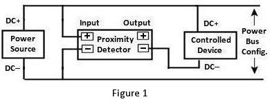
Figures 1 &
2 show two methods of wiring the proximity detector where simple DC power (+ & –
DC) will operate the controlled device. Examples would be to turn on LEDs or
start an effect that just requires power being applied to initiate the effect.
Figure 1 shows an easy way to power everything in an “accessory power bus”
configuration where the controlled device may be located near the detector. In
this situation, the DC+ output of the detector does not need to be wired because
the device is connected to the bus.
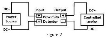
Figure 2 shows a “stand alone” type configuration. For either application the
distance between the detector and device to be controlled should be limited to a
maximum of 8 feet. Power source wires can be longer.
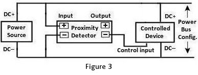
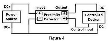
Figures 3 &
4 below show similar wiring methods but in this case the device to be controlled
requires its input control to be grounded (DC–) to initiate startup. This would
be typical for many of Ngineering’s Lighting and Sound special effects.
For any of
the above configurations, if the proximity detector is to control multiple
devices at the same time, it can sink a maximum of 200ma of current. This could
be 3 or 4 Little Sound effects, 2 or 3 Little Bigger Sounds, or multiple (5 or
6) Lighting effects.
Soldering
wires to the Detector:
Important
note:
A
low-wattage iron with a pointed tip should be used for connection of wires. Too
much heat or solder can easily damage the wires
or module and void the warranty.
We recommend
pre-tinning the solder pads and pre-tinning the wires to be connected. This will
minimize heat transfer.
Mounting:
Slots
are provided in the top of the mounting bracket for screws to affix the
assembly. Position the detector
with both ultrasonic sensors facing forward and at least 3 feet above the floor
surface to minimize dust accumulation (higher is better). If the display is
portable, a small piece of tape can be placed over the sensor faces to keep them
clean during transport.
Powering up
the detector:
Due
to component density and circuit board size, this circuit
DOES NOT
have protection against incorrect voltage polarity. Ensure + & – DC voltages
will be applied to the proper solder pads or
DAMAGE will occur.
Setting
detection distance:
Set the
range mode switch to the distance range desired for your application (3 foot
setting is the most common). Power up
the detector and place an object such as a chair back (or a person) at the
maximum distance you want the detector
to activate. An example would be 2 feet. Slowly turn the blue adjustment knob CCW until the LED just
turns off. If the LED was off at power up, turn the knob CW until the LED just
lights. The detector is now set to that distance for its maximum for detection.
© 2018 Ngineering