


Best viewed using:
Internet Explorer
or
Mozilla Firefox


N8131 Assembly and installation
Connecting the N8101 & N8101B:
Using the N8101 is very straightforward. Its tiny size will allow it to
be placed nearly anywhere.
Solder points #1 and #2 are the power
input connections. Power input to the N8101 can be up to 16-volts and can be
up to 25-volts for the N8101B, and can
be either analog DC, DCC. AC voltage can also be used but
is limited to the RMS equivalent value. Solder point #3 is
–DC output (or ground), and solder point #4 is +DC output. See figure 1.
Figure 1
Also included on the board is solder point #5. This is an optional connection point provided for +DC resisted voltage output to a polarity sensitive device such as an LED. Figure 2 below shows the back side of the board.
Figure 2
Shown
are the two solder pads provided for either an 1/8-watt or 1/4-watt
surface-mount type resistor. When a resistor is installed, the circuit
through to solder point #5 is completed so the resistor is in series with
the +DC output #5. Connecting a device such as an LED between #5 and #3 will
provide power for the LED.
Note: For proper LED operation, resistor
selection must be calculated based on maximum expected input and LED
voltage. If
you need help
to determine proper
resistance, please go here.
When connecting an LED to the module, proper polarity must be observed. LEDs are “polarity sensitive” and will not function if connected backwards. Connect the LED cathode (the – connection) to point #3 on the module and connect the LED anode (the +) to solder point #5.
Important
note:
A low-wattage iron with a pointed tip should be used for connection of
wires. Too much heat or solder can easily damage the wires, or the module
and void its warranty.
Also, all wires should be
pre-tinned before soldering them to the N8101. This will make connection
quick and easy and ensure excessive heat is not applied to any solder
points.
Flicker control:
Included in this package are tantalum polarized capacitors.
Tantalum capacitors are superior to other polarized capacitors because they
have a larger storage capacity for their size and do not “age” like other,
electrolytic polarized capacitors do. In modeling where small scale factors
dictate available space, these little jewels can be very useful for storing
an electrical charge and releasing it when input power is momentarily
interrupted. In model railroading, dirty spots on the track are a common
source for tiny power interruptions.
Polarized capacitors have a plus DC connection, and a minus DC connection.
By wiring them in parallel (all pluses connected together, & all minuses
connected together), their storage capacities (uf, or microfarads) are added
together.
NEVER
wire them in series with each other (end to end).
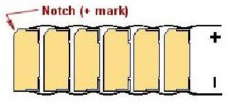
Because of their “boxy” shape and tiny size, they can be stacked
strategically to utilize the least amount of space possible. These
capacitors have a stripe and an angle at one end that identifies the plus
(+) DC connection. Figure 3 below shows an example of 6 capacitors stacked
and soldered in parallel. You can use the #26 solid wire in this package for
that purpose.
Putting it all together:
Since the capacitors are DC devices, they cannot
properly function with any other
type of input voltage. As a result, they
must be connected
“behind” the N8101/B DC Power Source module at
the output solder points
3 &
4. Input from
the track pickups connect to solder point
1
&
2.
See figure 1 on the
front of this instruction
for more detail.
We recommend using the two 4” segments of #32 black super-flex wire for
connections to points 1 & 2, because this wire is designed for repeated
flexing and can easily withstand the rotation of trucks on rolling stock
as they negotiate curved track. This flexing is what this wire is
designed for.
The red and black #32 hook-up wire can be used to connect the N8101/B
output solder points
3 & 4
to the capacitor “bank” connections, then on to whatever device(s) you
will be providing power to. Simply just cut these wires into whatever
lengths work for your project and strip and tin their ends before
attaching them to the N8101/B or the capacitor bank. Figure 4 below shows
a typical wiring diagram for connection of one of our Lighting Effects
Simulators.
© 2021 Ngineering