


Best viewed using:
Internet Explorer
or
Mozilla Firefox


Connecting the N8048 Structure Lighting Simulator
and
the N8048C Controller
N8048 Structure Lighting Simulator
Installing the N8048 is very straightforward. Its tiny size and thin construction will allow it to be placed in many locations, even in the smallest scale structures. Because the module has circuitry on both sides, care must be taken to be sure that the components or wires soldered will not make contact with any metal object (such as a locomotive frame) causing a short circuit.
Included with the module are three 6” lengths of #32 insulated wire. If necessary, these can be used for power and input control wires. If used, we recommend the red wire be used for the + DC connection. It would be connected to solder point 1 as shown in Fig. 1. This wire could also connect through a switch to the + DC connection for remote control of the lighting effect. The black wire should be connected to – DC and to solder point 2.
Revision A:
Any well regulated DC power source can be used to power this module providing the voltage is at least 6VDC and doesn't exceed 18VDC. Our N3512 and N3518 Power supplies are ideal for this use. Also, due to the very low power consumption, this device can also be powered by a battery, such as a standard 9-volt.
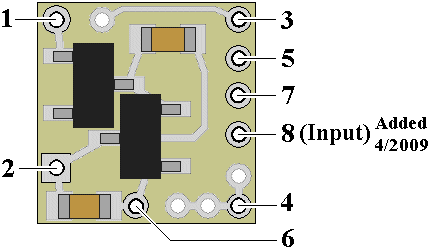
Figure 1
Important note: A low-wattage iron with a pointed tip should be used for connection of wires. Too much heat or solder can easily damage the wires, decoder or module and void the warranty.
Also, all connecting wires should be pre-tinned before soldering them to the module. This will make connection quick and easy and ensure excessive heat is not applied to the solder points.
Connecting LEDs
When connecting the LEDs, proper polarity must be observed. LEDs are “polarity sensitive” and will not function if connected backwards. The N8048 is configured to allow the connection of up to three (3) 20 ma LEDs with device voltages of 3.2-3.6 VDC. This covers Ngineering’s 2x3 white and Incandescent LEDs, Micro white and yellow-white LEDs, and Nano white LEDs, as well as many white LEDs available.
Using wire appropriate for the size of the LED and its placement in the structure, connect the LED cathode (the – connection) to point 3 on the module and connect the LED anode (the +) to solder point 4. Again, this LEDs will use the on-board current limiting resistor so it can be wired directly.
The N8048 is configured to support two (2) additional LEDs for a total of three (3). Each additional LED must be wired with an external resistor in series to limit the current flow through the LED. Included with this module are three 1/8-watt surface-mount resistors (two 81Ω resistors, plus a spare). These resistors are tiny for easy placement and have pre-tinned tabs so soldering is easy. The second LED’s cathode is to be wired to solder point 5 on the module. The resistor should be wired in series between this LED’s anode and point 6. The third LED's cathode is to be wired to solder point 7 on the module. The resistor should be wired in series between this LED’s anode and point 6. See Fig. 2 below for a complete overview of wiring.
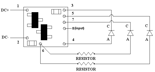
Figure 2
Once again, be sure to use a low-wattage soldering iron when connecting wires to the module. Our N40M2 12-watt Iron with either the N408I (iron clad) Needle Tip, or the N408X (bare copper) Needle Tip would be an excellent choice for this operation.
N8048C Structure Lighting Simulator Controller
A typical layout of the N8048C connection to multiple N8048 Structure Lighting Simulators is shown in Fig. 3 below.
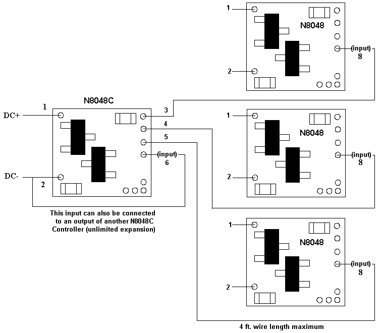
Figure 3
As noted above, The input solder point (pin 6) of the N8048C Controller can be connected to an output pin (3, 4, or 5) of another N8048C controller. This ability to cascade modules offers virtually unlimited expansion of Structure Lighting Control.
This completes hookup of our N8048 Structure Lighting and N8048C Control modules. We hope the added realism it provides enhances your enjoyment of the hobby.
© 2009 Ngineering