Secure Site
Shop with
Confidence
Best viewed using:
Internet Explorer
or
Mozilla Firefox
Connecting the N8013 Alternating Flasher
This flasher is part of a series that incorporates a state-of-the-art component which provides a constant 20 ma current source for LEDs connected to the flasher. This means any color 20 ma LEDs can be connected without the need of external current limiting resistors, multiple LEDs can be connected in series* and different colors of LEDs can be combined in the same series. All will operate at 20 ma and full brightness.
* A power supply of sufficient regulated DC voltage (not exceeding 16VDC) is required to support multiple LED in series. To determine power supply requirements, add all device voltages of the desired LED series together plus another 5 volts for the current source. This total is the minimum supply requirement and it must not exceed 16 VDC.
Using “common anode” products:
Some products made by Tomar, Z-Stuff, and NJ International’s Cross Bucks & Crossing Gates have their LEDs wired with one wire for the anodes of both LEDs. This is known as “common anode” wiring and our flasher is designed to support these type of products. However, if multiple common anode products are to be connected to a single N8013 Alternating Flasher unit, special wiring connections are required. See Wiring for multiple common anode products on the back of this instruction sheet
Connecting the N8013 Flasher:
Included with the flasher are two 6” lengths of #24 wire (red & black). If necessary, these can be used for connection to a regulated DC power source.
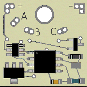
The black wire should be soldered to the – DC connection (upper right corner of the flasher board—see Fig 1). The red is soldered to the +DC (upper left corner of the board) . If desired, the red can be wired through a switch to turn the flasher on and off.

Figure 1
LEDs are connected to the flasher with their anodes or + side wired to the A solder point on the flasher and the cathode or - side of one LED (or series group) to the B solder point and the second LED (or series group) connected to the C solder point.
If multiple LEDs are wired in a series group, the anode of the first LED in the group connects to A and the cathode of the last LED in the group connects to either B or C.
LEDs wired in a series group are always to be connected anode to cathode (daisy-chain style wiring).
Adjusting LED brightness
For certain applications it may be desirable to have the LED or LEDs connected to this flasher operate at less than full brightness (less than 20 ma current). For this reason, solder pads are included on the back of the flasher board (marked B & C to correspond with the front) for placement of a resistor to compensate current source output down from 20 ma. Fig. 2 below shows a resistor placed across the C solder pads).

Figure 2
To calculate the resistor value, divide the LED device voltage by the milliamps (ma) you wish to reduce. This will give the value in ohms of the resistor (we recommend using a 1/4 watt resistor).
Example: Reduce the current output from 20 ma to 10 ma with a red LED having a device voltage of 1.7. Divide 1.7 by 0.010 (10 ma). The result equals 170. Use a 170 ohm resistor. To reduce current through a series of LEDs, add the device voltages in the series together then divide by the amount of ma current reduction.
To balance brightness of both sides of the alternating flasher, an additional resistor of equal value to the one connected to the C solder pads, should also be connected to the B solder pads.
Note: This brightness adjustment procedure applies only to LEDs connected through the on-board current source. If multiple common-anode products are to be connected (as described below), those additional products must have brightness adjustments made by increasing the resistor values of each resistor connected to their respective LEDs (see Fig. 3).
Wiring for multiple common anode products
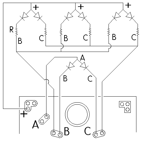
Fig. 3 below shows as an example, 4 pair of common anode LEDs wired to the alternating flasher. As noted on the front of this instruction, one pair is wired as we would connect any 2 LEDs to the flasher, with the anodes (+) hooked to the A solder point and the 2 cathodes hooked to B & C respectively. Connected this way, they can use the on-board current source and won’t require current limiting resistors to protect the LEDs.
The other 3 pair of LEDs (or however many pairs are being used depending on the limits of the power source) must have their common anodes connected directly to the + DC solder point (upper left corner of the flasher). This is necessary because the on-board current source is designed for 20 ma LEDs and multiple common anode devices cannot be wired in series, so their currents add together. In the example below, when the 3 “B” LEDs are on they will draw 60 ma of current, more than the source can provide. Also, since these 3 pair are connected directly to the +DC, the LEDs must have current limiting resistors in between their cathodes and the connections B or C.
Determining the correct resistor for these LEDs is very straightforward and is a function of the voltage of your power source and the device voltage of the LEDs being used. To calculate proper resistor value, please refer to our section on using resistors with LEDs here and our LED calculators here. Also, the basic details are on every LED package we sell. Should you need additional help, don’t hesitate to contact us we’ll be happy to assist you.

Figure 3
A mounting hole is provided for a #4 or 4-40 screw for mounting the flasher. A small spacer or non-conducting washer should be placed on the underside so the back of the board is not in contact with a surface or object which might short-circuit the board.
Using DCC Track Power
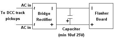
While it is always preferable to use track power exclusively for things running on the track, there may be situations where it is necessary to tap into track power to drive various stationary devices. Should this be the case in a DCC environment, our Super Flashers can be powered from the track with the addition of two readily available components: a bridge rectifier (our N301S would work just fine), and a polarized (electrolytic) capacitor. Figure 4 below is schematic diagram of the connections required.

Figure 4
DCC track power is such that to devices requiring plain DC voltage, it looks like AC power. That is because voltage levels on each track go both + and –. The DCC decoders in locomotives “descramble” the track signals and provide correct polarity so their motors can function normally. What this small circuit is doing is running the DCC voltages through a bridge rectifier to “filter” the track voltages so that + DC is output on the bridge’s + terminal and –DC is output on the bridge’s – terminal. This DC signal is still a bit “bumpy” (not a smooth DC signal) so we add the capacitor to smooth it out. As a result, the voltage going into our flasher is smooth DC and the flasher works normally.
One caution: Make sure the DC voltage level at the output of the bridge rectifier does not exceed 16-volts or the Super Flasher will be damaged. Some DCC systems (typically larger scales) can produce voltage levels higher than 16-volts.
This completes connection of the alternating flasher. We recommend a thorough re-inspection of all connections and placement of the flasher be performed prior to applying power .We hope you enjoy the added realism our flasher provides.
© 2008 Ngineering

