Secure Site
Shop with
Confidence
![]()
![]()
![]()
![]()
![]()
![]()
![]()
![]()
![]()
![]()
![]()
![]()
![]()
![]()
![]()
![]()
![]()
![]()
![]()
Best viewed using:
Internet Explorer
or
Mozilla Firefox


Connecting the NLA8049 & NLA8049A Chase Light Simulator
Installing the NLA8049 and NLA8049A are very straightforward. Their tiny size and thin construction will allow them to be placed in many spaces too small for even the smallest Z-scale decoder. Because the module has circuitry on both sides, care must be taken to be sure that the components or wires soldered will not make contact with any metal object (such as a locomotive frame) causing a short circuit.
Included with the module are two 6” lengths of #32 insulated wire. If necessary, these can be used for power input wires.
NLA8049/A (analog) input power connections:
The NLA8049/A Simulator is configured for analog (DC) operating environments. They will function normally with track voltages ranging from 3.2 to 16-volts DC. The circuit includes a Schottky barrier diode to protect the module from reverse input voltage polarity. This means when it is wired the normal "engineer's side is the +DC track side", the effect is fully operational. when running in reverse "fireman's side is the +DC track side) the effect is not in operation. For many lighting effects, this will not be a problem because they are intended for forward operation.
For those effects that need full bi-directional operation, one of our N8101 DC Power Source circuits can be added in front of the effect simulator board to eliminate DC polarity issues. The N8101 contains a very-low voltage-drop Schottky bridge rectifier which will slightly raise the startup voltage threshold of the lighting effect by about 0.2-0.4 volts. Figure 2 below below is schematic diagram of the connections required.
While these Simulators are typically used with track powered Analog (DC) operations, they also lend themselves nicely to battery operation. This may offer an advantage in many structural displays and dioramas where AC power is not available for power supply plug-in.
All solder connections explained below
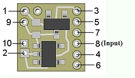
Figure 1
Connecting LEDs
When connecting the LEDs, proper polarity must be observed. LEDs are “polarity sensitive” and will not function if connected backwards. The N8049 is configured to allow the connection of six (6) 20 ma LEDs with device voltages of 3.2-3.3 VDC. This covers Ngineering’s white and Incandescent LEDs, Micro white and yellow-white LEDs, and Nano white LEDs, as well as many white LEDs available.
The N8049A version of this simulator is for LEDs six (6) 20 ma LEDs with device voltages of 1.75-2.0 VDC. This covers Ngineering’s Micro, Nano, Subminiature and 5mm wide-angle red and yellow LEDs, as well as many red and yellow LEDs available.
In the wiring diagram below (Fig.3), the LEDs are shown with numbers 1 through 6 for clarity and have their anode (+) and cathode(-) connections identified by A and C.
Note that the six LEDs are essentially connected as 3 series-pair groups (1 to 2, 3 to 4, 5 to 6).
Also note that all of the odd numbered LEDs have their anodes connected together and are then connected to the solder point 4.
Further, note that all of the even numbered LEDs have their cathodes connected together and are then connected to the solder point 6.
Unlike our traditional Simulators, these new low-voltage modules have two on-board current limiting resistors. The second resistor can be connected either to the circuit's +DC voltage or to it's –DC (ground) by solder jumpering either of two pairs of jumper pads on the rear-side of the module. Figure 2 below show the location of the resistors and solder jumper pads. Never place solder on both pairs of jumper pads, this would destroy the Simulator. See Fig. 3 below for a complete overview of wiring.
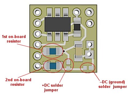
Figure 2
For the NLA8049/A Simulators to function correctly, place a small blob of solder across the –DC (minus DC) jumper pads. This will ensure the connected LEDs will have their cathodes connected to ground (–DC).
The N8049 controls the lighting of the 6 LEDs with control wires connected as follows:
Solder point 3 is wired to the junction of LED 1 cathode and LED 2 anode.
Solder point 5 is wired to the junction of LED 3 cathode and LED 4 anode.
Solder point 7 is wired to the junction of LED 5 cathode and LED 6 anode.
Using wire appropriate for the size of the LEDs and their placement in the project, connect the LEDs as shown in Fig. 3 below.
Figure 3
Once again, be sure to use a low-wattage soldering iron when connecting wires to the module. Our N40M2 12-watt Iron with either the N408I (iron clad) Needle Tip, or the N408X (bare copper) Needle Tip would be an excellent choice for this operation.
This completes hookup of our NLA8049/A Chase Light modules We hope the added realism it provides enhances your enjoyment of the hobby.
© 2014 Ngineering